
Tutorial · Intermediate · 30 min
Wheel Slip: Why Odometry Drifts and How to Fight It
The wheels turn further than the robot moves. Where the traction limit is, why a pivot turn always slips, and why systematic slip is the dangerous kind.
Introduction
Drive a robot in a one-metre square, four 90° turns, back to the start. It does not arrive. Calibrate the wheel diameter and the track width until the straight lines are exact, run it again, and it still does not arrive — and it misses by a different amount on carpet than on tile.
This site names wheel slip as the reason on the odometry page, the encoder page, the micromouse project and half a dozen others. What none of them says is what slip actually is, how much of it you have, or which parts of it you can do something about.
An encoder measures the wheel, not the ground
That sentence is the whole topic.
An encoder counts wheel rotation. Odometry needs ground travel. Those are the same number only while the contact patch is not sliding, and the difference is the slip ratio — the fraction of wheel motion that did not become robot motion:
slip = (wheel travel − ground travel) / wheel travelTwo consequences that shape everything below:
Slip is invisible from inside. No encoder, however good, can detect it, because the encoder is measuring the thing that moved. This is the same blindness as gearbox backlash and it has the same cure: something that measures the outside world.
It is not noise. Noise averages out; slip generally does not, and the reason is the next-to-last section.
The traction budget
A tyre can only push as hard as friction lets it:
F_max = µ × NN is the weight actually pressing on the driven wheels — not the robot’s whole weight. The same product sets how hard the robot can push something else, which is the one job where you want the traction limit to be as high as possible rather than merely high enough. A typical 2WD chassis with a castor carries somewhere around half to two thirds of its mass on the drive axle, and the rest is doing nothing useful for traction.
Divide through by mass and the ceiling is an acceleration:
a_max = µ × (weight fraction on driven wheels) × g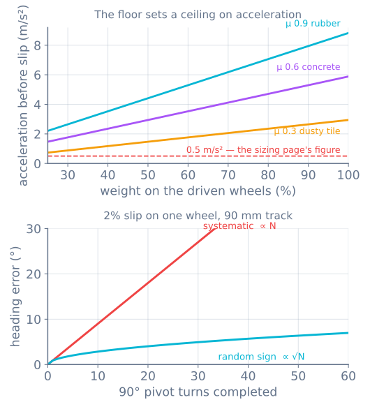
The useful reading of the top panel is that straight-line driving is rarely traction-limited on a hobby robot. Even the worst surface there gives more than three times the acceleration a typical design asks for. If your robot is slipping in a straight line, you are commanding a step change rather than a ramp — which is what a motion profile exists to prevent.
Turning is a different story.
A pivot turn always slips
A differential-drive robot has fixed wheels. They can roll forwards and backwards and they cannot move sideways — but a pivot on the spot requires exactly that.
Rotate the chassis about its centre and every point on each tyre’s contact patch traces an arc, while the wheel is only able to roll along a straight line tangent to it. The difference is scrub: the tyre is dragged sideways across the floor for the whole turn. A wide contact patch scrubs more than a narrow one, and a castor that does not swivel freely fights the turn as well.
So a pivot turn is not a manoeuvre that might slip. It is one that is slipping by construction, and its encoder-derived heading is wrong every time by roughly the same amount, in the same direction.
That last clause is the problem.
Systematic slip is the dangerous kind
Take a 90 mm track. A 90° pivot rolls each wheel 70.7 mm. Let one wheel lose 2% of that to scrub and the heading comes out 0.9° short — a number small enough to be invisible on any single turn.
Now run a maze. The bottom panel of the figure shows the two futures:
- Random sign — some turns short, some long. Error grows as √N. After 50 turns it is about 6°, and it is genuinely a random walk you can model.
- Systematic — every left turn scrubs the same way for the same reason. Error grows as N. After 50 turns it is 45°, and the robot is driving down a corridor it thinks is somewhere else.
Real robots are much closer to the second. The scrub comes from geometry that does not change between turns, so the error does not either. This is why “it drifts a bit” becomes “it is lost” over a run, and it is why the micromouse needs a gyro rather than better encoders.
Finding out how much you have
Three tests, cheapest first.
Drive a straight line and measure. Mark the floor, command exactly 1000 mm, measure what you got. Repeat on two surfaces. A consistent scale error is calibration; an error that changes with surface is slip.
Pivot 10 times and look. Command ten 90° turns — that is 900°, or two and a half full rotations. Mark the start heading and measure the finish. Divide the error by ten. This amplifies a per-turn error that is otherwise unmeasurable, and it is the single most useful thing on this page.
Compare the encoders with a gyro. If you have an MPU-6050, integrate its Z rate through a turn and compare with the encoder-derived heading. The disagreement is the slip, measured directly, live, with no floor markings. Where they differ the encoders are wrong — the gyro does not care what the wheels did.
A current spike with no matching acceleration is the other live signature: the motor is working and the robot is not moving.
What actually helps
Ramp everything. A commanded step in wheel speed asks for infinite acceleration, and the tyre supplies what it can and slides for the rest. Profiling the command is free and it is the biggest single win.
Turn in an arc where you can. An arc rolls both wheels forwards at different speeds and scrubs far less than a pivot. Where the map allows it, prefer it — this is also the backlash fix, because an arc never reverses a wheel either.
Get the weight over the drive wheels, and keep the castor free. Weight on an undriven castor is weight not making traction.
Narrow the contact patch if you pivot a lot. Wide grippy tyres help acceleration and hurt pivots; the trade is real and it is worth choosing deliberately.
Do not chase µ with more grip alone. More friction means the slip happens later, not that odometry becomes correct. It is a margin, not a fix.
What nothing helps
Wheel odometry is dead reckoning. It has no reference to the world, so slip, backlash and diameter error accumulate and are never corrected — this is the same unbounded drift the motor-control path warns about, and it is a property of the method rather than a defect in your build.
The fix is a second opinion:
- A gyro corrects heading, which is the error that hurts most, and is cheap.
- Wall or line references reset lateral position every time you see one — how a wall follower stays true down a corridor.
- A map — scan matching or SLAM — corrects both, at the cost of a lidar and a great deal more compute.
Odometry is excellent over a metre and worthless over a hundred. Design around that rather than trying to fix it.
When it goes wrong
| Symptom | Usually |
|---|---|
| Square never closes despite perfect straight lines | Pivot-turn scrub; measure it with the ten-turn test |
| Distance right on tile, short on carpet | Slip, not calibration — the error follows the surface |
| Heading error grows steadily in one direction | Systematic slip; a gyro is the cheap fix |
| Error grows quickly at first, then plateaus in a corridor | The wall is correcting you — that is the reference doing its job |
| Robot slips only when starting | Commanded step instead of a ramp |
| Gyro and encoders disagree during turns | Correct — that disagreement is the measurement |
| More grippy tyres did not fix odometry | Grip raises the slip threshold; it does not make encoders honest |
| Only one wheel seems to slip | Weight distribution or a binding castor, not the motor |
The habit worth taking away is the ten-turn test. It converts an error nobody can see into a number, and once you have the number you can tell whether you need a gyro, a ramp, or nothing at all.
The drivetrain where slip is the mechanism
Everything above treats slip as a fault. On a mecanum base it is the design: the rollers let go sideways on purpose, and that is how the robot moves sideways at all. The consequences are worth stating plainly, because they change what you should measure rather than how hard you should try.
- Sideways odometry is the weakest number on the robot, not a tuning problem. The encoder is bolted to the wheel and the wheel is deliberately not the floor.
- There is one free check and it is half blind. Four wheels and three degrees of freedom
leave a spare equation —
FL + FR = RL + RRon any rigid, gripping chassis — so the residual catches one wheel slipping and cannot see all four slipping together. The derivation is here. - The fix is unpowered wheels. Omni dead wheels on spring mounts carry no torque, so they do not slip under command, and they turn the worst number on the robot into the best one.
Drop the grip slider and watch the encoders keep insisting the robot arrived.
Explore the graph
Part of these builds
Projects and learning paths that include this tutorial.
Further reading