
Tutorial · Beginner · 17 min read
Read Quadrature Encoders for Distance and Speed
Decode a quadrature encoder, convert counts into wheel distance and velocity, handle direction and rollover, and calibrate measurements on a real robot.
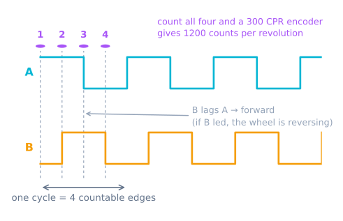
A wheel encoder turns rotation into digital pulses. Count those pulses and you can measure how far a robot travelled; count them over time and you can estimate speed. A quadrature encoder provides two pulse channels, A and B, shifted by one quarter of a cycle. Which channel changes first reveals direction.
Encoders measure relative motion, not an absolute position. The count becomes meaningful only after startup or an intentional reset, and it becomes useful only after you define exactly how many counts represent one wheel revolution.
Read the two-channel pattern
The valid quadrature states are 00, 01, 11, and 10. Turning one way walks through that sequence; turning the other way reverses it. Only one bit should change at a time. A transition such as 00 directly to 11 means an edge was missed or noise corrupted the signal.
There are three common counting modes:
- 1× decoding: count one edge on channel A per cycle.
- 2× decoding: count both edges on channel A.
- 4× decoding: count every edge on both channels.
A data sheet that says 12 pulses per revolution may therefore produce 12, 24, or 48 software counts per encoder-shaft revolution. Add the gearbox ratio if the encoder is mounted on the motor rather than the wheel. Write the complete convention beside the constant; unexplained factors of two and four are a frequent odometry bug.
Connect the signals correctly
Determine whether the outputs are push-pull, open-collector, or open-drain. Open outputs need pull-up resistors, which may be internal or external depending on edge rate and wiring. Confirm that the signal voltage is safe for the controller—5 V encoder output can damage a 3.3 V input.
Keep the cable away from motor leads. For longer runs, use the cable and termination guidance from the encoder manufacturer. A clean digital edge is more valuable than trying to repair false counts in software.
Turn the wheel slowly by hand before running the motor. Both channels should alternate between valid logic levels. If one is stuck, fix the wiring before debugging code.
Decode direction without losing counts
For modest speeds, trigger an interrupt whenever channel A changes and sample B to determine direction:
volatile long encoderCount = 0;

void onEncoderA() {
  bool a = digitalRead(ENCODER_A);
  bool b = digitalRead(ENCODER_B);
  encoderCount += (a == b) ? 1 : -1;
}
The sign depends on channel order and physical mounting. Swap A and B or negate the result so forward wheel motion gives a positive count. Do this once at the hardware boundary instead of scattering sign changes through odometry code.
At high edge rates, repeated digitalRead() calls may be too slow. Use a hardware quadrature peripheral, a proven platform encoder library, or direct port access appropriate to the controller. Estimate the worst case before choosing: edges per second = counts per wheel revolution × maximum wheel revolutions per second.
Keep interrupt work short. Update the count, then return. Printing, floating-point conversions, and control calculations belong in the main loop.
Convert counts to wheel distance
Let N be decoded counts per wheel revolution and D be effective wheel diameter. Wheel circumference is πD, so:
distance = count × πD / N
For a 65 mm wheel and 1,440 decoded counts per wheel revolution, each count represents about 0.142 mm. That mathematical resolution is not the same as real accuracy: tire compression, wheel slip, and diameter error are usually larger.
Read a multi-byte counter safely. On a small microcontroller, an interrupt can update it halfway through the main loop’s read. Briefly disable interrupts or use the platform’s atomic facility:
noInterrupts();
long snapshot = encoderCount;
interrupts();

float distanceM = snapshot * (PI * wheelDiameterM) / countsPerWheelRev;
Use a sufficiently wide signed counter and calculate differences between snapshots. Unsigned modular subtraction can handle rollover, but only if the types and sampling interval are intentional.
Estimate speed without amplifying noise
At a fixed sample interval, compute the count difference:
velocity = (newCount - oldCount) × distancePerCount / elapsedTime
Short intervals respond quickly but quantize low speeds into zero and one-count jumps. Long intervals are smoother but add lag. Start near the control-loop period, then average a few samples only if the controller actually needs it.
For very slow motion, measuring time between edges can be better than counting edges inside a fixed window. Whichever method you use, timestamp with a monotonic clock and use the measured elapsed time rather than assuming every loop executes perfectly on schedule.
Calibrate on the complete drivetrain
Mark the wheel and rotate it exactly ten revolutions while recording counts. Dividing by ten reduces the effect of stopping between individual edges. Then command the robot along a measured straight line, compare encoder distance with floor distance, and adjust effective wheel diameter.
Calibrate left and right wheels separately. If the robot reports equal distances but curves, the two effective diameters or drivetrain gains differ. Preserve separate scale factors; real tires and gearboxes need that calibration knob.
Repeat at a second speed. A large change suggests slip, loose hubs, missed edges, or a timing problem rather than a simple diameter error.
Diagnose bad readings
- Count changes while stationary: electrical noise or floating inputs; inspect signals and pull-ups.
- Count magnitude is exactly 2× or 4× wrong: the software decoding mode and data-sheet pulse definition disagree.
- Direction flips randomly: one channel is noisy or sampled too late; verify edge quality and decoding method.
- Counts freeze at speed: the controller cannot service the edge rate; use hardware decoding or reduce interrupt overhead.
- Distance is repeatable but wrong: calibrate effective wheel diameter and gearbox ratio.
- Distance varies by surface: the encoder measures wheel rotation, not ground truth; wheel slip is real motion uncertainty.
Reliable counts are the input to differential-drive odometry, while velocity feedback can close the motor loop explored in the PID Controller Simulator. That pose is also the input every path follower assumes, which is why its error becomes theirs.
Next
Counting is only half of it. A measured speed is worth having because you can hold it — see closed-loop wheel velocity control, which turns PWM from a voltage into a speed and is what stops a robot curving because one motor is tired. On a holonomic base that stops being a nicety: the four wheel-speed ratios are the steering, and open loop has nothing to hold them with.
Explore the graph
Part of these builds
Projects and learning paths that include this tutorial.
- ProjectBuild a GPS Waypoint Rover That Drives Itself
- ProjectBuild a Mecanum Robot That Drives Sideways
- ProjectBuild a Micromouse: A Flood-Fill Maze-Solving Robot
- ProjectBuild a Room Coverage Robot That Sweeps a Floor
- ProjectBuild a ROS 2 Robot That Sees and Drives to a Marker
- ProjectBuild a Self-Balancing Robot With an MPU6050 and PID
- Learning pathHolonomic Drive: Move Sideways Without Turning
- Learning pathMotor Control for Robots: A Learning Roadmap
- Learning pathPath Following for Robots: A Learning Roadmap
Further reading