
Build a Mecanum Robot That Drives Sideways
A robot that strafes a 1 m square, comes back within 5 cm without ever turning, and keeps driving the same way across the floor while you spin it.
What you are building
A four-wheel robot that can move in any direction on the floor without turning first, and can turn without changing where it is going. Push it sideways down an aisle it barely fits in; hold a camera pointed at something while orbiting it; correct 3 cm off a line by stepping 3 cm, instead of arcing out and arcing back.
This is the first robot on this site with three independently controllable velocities instead of two. It is also the first one whose drivetrain is genuinely harder than its sensors, which is why almost the whole build is motors, encoders and control loops.
The acceptance test is deliberately blunt: drive a 1 m square by strafing, and come home within 5 cm with the heading unchanged. No differential-drive robot can attempt that test at all.
The number that runs the project
Everything on this build comes back to one constant:
k = lx + lywhere lx is half the wheelbase (front axle to rear axle, halved) and ly is half the track (left wheels to right wheels, halved). On the reference build, 75 mm and 85 mm, so k = 0.160 m.
That single number couples rotation to the wheels. Get it wrong and the robot still drives — but a pure spin command creeps across the floor, and a pure strafe curves, because rotation and translation are bleeding into each other. Measure wheel centre to wheel centre, not the chassis plate, which is usually wider than you think.
The other numbers worth writing on the chassis in marker before you start:
| Quantity | Reference build | Where it comes from |
|---|---|---|
| Wheel radius r | 48.5 mm | 97 mm mecanum wheels |
| Counts per wheel revolution | 1440 | 12 CPR × 30:1 × 4 quadrature edges |
| Metres per count | 212 µm | 2πr ÷ 1440 |
| Wheel top speed V_MAX | 0.60 m/s | Measured on blocks, then derated 15% |
| Diagonal ceiling | 0.424 m/s | V_MAX ÷ √2, and no motor upgrade removes it |
| Acceleration ceiling | 5.9 m/s² | μg/√2 at μ = 0.85 — mass cancels out |
Bill of materials
| Item | Qty | Approx. cost | Notes |
|---|---|---|---|
| Mecanum wheels, 80 or 97 mm | 4 | £28–70 | Buy as a set of four — two left-handed, two right-handed |
| N20 gearmotor with encoder, 30:1 | 4 | £9–14 each | Match them. 100–250 rpm at the wheel is the useful band |
| TB6612FNG dual H-bridge | 2 | £4–8 each | An L298N works and wastes ~3 V doing it; on a 2S pack that is most of your speed |
| ESP32 dev board | 1 | £6–12 | Four PWM channels, four encoder interrupt pairs, and Wi-Fi telemetry for free |
| MPU6050 IMU | 1 | £2–4 | Mount it flat, away from the motors, on the chassis centre line |
| 2S LiPo, 1500–2200 mAh, 25C | 1 | £12–20 | Sized on current, not capacity — four motors stall at ~5 A total |
| 5 V BEC or buck converter | 1 | £3–5 | Do not run the ESP32 off the motor rail |
| Chassis plate, 200 × 180 mm | 1 | £10–25 | Laser-cut acrylic, 3 mm aluminium, or cut your own |
| Motor mounts, hubs, fasteners | 1 set | £8–15 | Match the hub bore to the motor shaft — 3, 4 or 6 mm |
| Bulk capacitor, 470 µF | 2 | £1 | One across each driver’s motor rail |
£90–170 total. The wheels and the fourfold motor count are where a two-wheel robot’s £50 becomes this.
How it all connects
        2S LiPo ──┬── 470 µF ── TB6612FNG #1 ── FL motor ── FL encoder ─┐
                  │                         └── FR motor ── FR encoder ─┤
                  ├── 470 µF ── TB6612FNG #2 ── RL motor ── RL encoder ─┼── ESP32
                  │                         └── RR motor ── RR encoder ─┘   (4 PWM,
                  └── 5 V BEC ──────────────────────────────── ESP32 ──────  8 GPIO,
                                                                   │         I²C)
                                                   MPU6050 ── I²C ─┘
Three wiring decisions that are not obvious:
- The ESP32 gets its own regulator. Four motors starting together drop the pack hard, and a controller sharing that rail browns out and reboots mid-command. It looks exactly like a firmware crash. Read the power budget tutorial before blaming your code.
- A bulk capacitor across each driver. 470 µF close to the board. H-bridges draw in bursts and the lead inductance turns those bursts into spikes.
- The IMU goes on the centre line, flat, and as far from the motors as the plate allows. Yaw drift is bad enough without a magnetic field from four motors in it.
Build it in milestones
Each one has a test. Do not carry a failure forward — on a four-motor robot they multiply.
1. Wheels on, and the X check
Bolt the four wheels on and stand directly over the robot. Follow the line of the rollers you can see on top of each wheel.
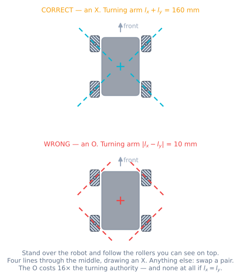
Test: those four lines aim at the middle of the robot and draw an X. If they draw a diamond, swap two wheels diagonally. Pass: an X. This is a five-second check that saves a day.
2. Each motor individually
Wire all four, and write a sketch that drives one wheel at a time at 40% for a second.
Test: call each one and confirm the right wheel turns the right way. Pass: four wheels, four correct directions, no swapped pairs. Fix wiring in hardware, not with minus signs in code — you will lose track.
3. Encoders
One revolution of each wheel, turned by hand.
Test: print the count. Pass: within 2% of 1440, and positive when the wheel turns forward. A count that jumps or runs backwards means you are interrupting on one channel instead of two, or reading a volatile long without disabling interrupts.
4. Kinematics on blocks
Put the robot on blocks and command a pure strafe.
Test: diagonal pairs oppose — front-left and rear-right go one way, front-right and rear-left the other. Pass: that exact pattern. Then command a pure spin: left side one way, right side the other. If a wheel disagrees, it is in the wrong corner and step 1 lied to you.
5. One velocity loop
Tune feedforward then PI on a single wheel, on blocks, then under load.
Test: command 0.3 m/s and press a finger on the tyre. Pass: the speed holds and the PWM visibly rises. Do this once properly; the other three are copies with their own kS and kV.
6. All four, straight line
Four loops, 100 Hz, on the floor. Drive 3 m straight.
Test: measure the lateral drift at the end. Pass: under 20 mm, and repeatable across three runs. Open loop this is typically 80–200 mm and different every time.
7. Strafe 1 m
Test: drive exactly one metre sideways and measure both the distance and the heading change. Pass: within 5 cm, heading within 3°. A consistent curve means the k constant is wrong; a random one means a velocity loop is not holding.
8. IMU and field-oriented
Bias-calibrate at boot, add the heading reset button.
Test: hold the stick forward and spin the robot by hand through a full turn. Pass: it keeps travelling the same way across the floor. Standing still, yaw drifts less than 3° per minute.
9. The square
The acceptance test. Drive 1 m forward, 1 m right, 1 m back, 1 m left, with no rotation commanded anywhere.
Test: distance from the start point, and heading change. Pass: within 5 cm and 3°.
What good looks like
| Measurement | First attempt, open loop | Tuned, closed loop |
|---|---|---|
| Lateral drift over a 3 m straight | 80–200 mm, varies with battery | Under 20 mm, repeatable |
| 1 m strafe accuracy | 10–20 cm, with a visible curve | Within 5 cm |
| Heading change over the strafing square | 10–30° | Under 3° |
| Top diagonal speed | Whatever survives clipping | 0.42 m/s — the √2 ceiling, reached cleanly |
| Speed as the pack sags 8.4 → 7.0 V | Drops ~17% | Unchanged until the motors saturate |
| Odometry error over the square | Not worth measuring | 2–5 cm on a good floor, much worse on a dusty one |
That last row is honest rather than disappointing. On this drivetrain the rollers slipping is the mechanism, so the odometry is the weakest number on the robot even when everything works. Build the expectation in rather than chasing it.
Hardware notes that matter
Wheel handedness is a set property. Two singles ordered separately from the same listing are very often the same hand. Check before you drill anything.
Every roller must spin freely. Flick each one by hand before the wheels go on. A seized roller turns that corner into an ordinary wheel pointing 45° off, intermittently, which reads exactly like a software bug.
Mecanum wheels are heavy. 180–400 g each, so up to 1.6 kg of the robot is wheels, and that is rotating mass on the ends of the moment arms. It makes the robot feel sluggish and it is why the acceleration ceiling matters.
The floor is a component. Polished concrete and vinyl are around μ = 0.8. A dusty gym floor, a coat of hairspray somebody used on a different robot, or a join in the lino will halve it locally, and the robot will change behaviour as it crosses. Watch what μ = 0.25 does before you blame the tuning.
When it goes wrong
| Symptom | Cause | Fix |
|---|---|---|
| Forward fine, strafing curves and spins | A wheel in the wrong corner | The X check; the kinematics residual will be large and steady |
| Strafes the opposite way to the command | All four wheels mirrored | Swap the left pair with the right pair |
| Spinning on the spot also translates | k wrong, or measured on the chassis | Re-measure wheel centre to wheel centre |
| Robot resets when all four motors start | Brown-out, not a crash | Separate regulator for the ESP32; bulk caps; check pack internal resistance |
| Diagonal much slower than straight | The √2 ceiling — working as designed | Nothing to fix |
| Leans out of corners under any automatic control | Per-motor clipping instead of scaling the command | Scale by the worst wheel |
| Drives well by hand, hopeless autonomously | Odometry, not control | IMU for heading; keep runs short; consider dead wheels |
| One wheel always saturated | Over-commanded, or that motor is the weak one | Lower V_MAX to what all four can actually hold |
| Encoder counts drift over minutes | Missed edges at speed | Interrupt on both channels; check the ISR is short |
Where to take it next
Dead wheels. Two or three unpowered omni wheels on spring mounts, with their own encoders. They carry no torque so they do not slip, and they turn the worst number on this robot into the best one.
Holonomic path following. Pure pursuit and Stanley assume a robot that steers. A base that can strafe can do better — track the path position and the heading independently, because you have separate actuators for them.
A camera on a base that holds heading. The natural pairing: a vision pipeline is far easier when the camera can stay pointed at the target while the base repositions. That is the thing holonomic drive is actually for.
ROS 2. This drivetrain is the first one here where cmd_vel’s linear.y — explicitly ignored by a differential-drive robot — finally means something. Swapping the twist-to-wheels function for the four-row mecanum version is most of the work.
Project roadmap
The build path
Follow the tech tree from parts to a robot that follows a taped line. Each node unlocks when its prerequisites are done, and your progress saves on this device.
0 / 17 done
Components
- ChassisMecanum Wheel SetFree rollers at 45° turn four ordinary motors into a robot that can move sideways.
- ActuatorN20 Encoder GearmotorA metal-gearbox micro motor with an encoder on the back, so the robot knows how far it has actually gone.
- DriverTB6612FNG Motor DriverA MOSFET H-bridge that keeps the volts you actually paid for.
- ControllerESP32A dual-core microcontroller with Wi-Fi and Bluetooth—the wireless step up from an Uno.
- SensorMPU-6050 IMUA six-axis motion sensor—how a robot feels its own tilt, turn, and acceleration.
- PowerRobot Battery & Power PackThe difference between a robot that runs and one that keeps resetting.
Tutorials in this path
- Beginner · 25 minHolonomic Drives: Omni, Mecanum, Swerve ComparedFour drivetrains, three degrees of freedom, and what each one charges you for them.
- Intermediate · 35 minMecanum Wheel Kinematics: Four Wheels, Three AxesOne roller at 45° gives you the whole matrix — and a fourth equation nobody uses.
- Intermediate · 35 minClosed-Loop Wheel Velocity Control With EncodersFeedforward does the work, the integrator cleans up, and the robot finally drives straight.
- Intermediate · 25 minField-Oriented Drive: Make Forward Mean ForwardRotate the stick by minus the heading, and the robot stops arguing with the driver.
- Beginner · 17 min readRead Quadrature Encoders for Distance and SpeedTurn quadrature encoder pulses into reliable wheel direction, distance, and velocity measurements.
- Intermediate · 30 minWheel Slip: Why Odometry Drifts and How to Fight ItEvery odometry page says slip ruins the estimate. This is what slip is and what it costs.
- Beginner · 30 minWhy Your Robot Resets When the Motors StartThe reset that looks like a code bug is almost always the battery. Budget the current, then measure the sag.
- Beginner · 30 minWhy delay() Breaks Robots: Timing With millis()A robot sitting in delay() is blind. Replace it with millis(), and get the rollover comparison right.
Practise before you wire
Tune it in the live simulator
The build path routes through a browser lab. Find gains that follow the track cleanly here, then transfer them to the real robot.
Frequently asked questions
Can I build this with an Arduino Uno?
Not comfortably, and the reason is pin count rather than processing power. Four wheels need four PWM outputs and four quadrature encoders need four interrupt-capable pin pairs. An Uno has six PWM pins spread over three timers — and the moment you use the Servo library or tone(), two of them stop working — and exactly two external interrupt pins. You can bodge it with pin-change interrupts and give up on one encoder, but you will spend the weekend fighting the board instead of the robot. An ESP32 or a Mega 2560 costs a few pounds more and removes the entire problem. This build uses an ESP32 because it also gives you Wi-Fi telemetry, which is genuinely useful when you are tuning four control loops at once.
How much does a mecanum robot cost to build?
Around £90–170 depending on wheel size and motor quality, which is roughly double an equivalent two-wheel robot. The increases are in predictable places: four mecanum wheels instead of four plain ones is the single biggest line, four motors instead of two, four H-bridge channels, four encoder cables, and a bigger battery because four stalled gearmotors is twice the worst-case current. The controller upgrade catches people out — budget for it at the start rather than after the chassis is drilled.
Why does my mecanum robot drive fine forward but spin when strafing?
One wheel is in the wrong corner, and this is by a wide margin the most common mecanum build error. Forward looks normal because the sideways components still mostly cancel; it is the strafe that exposes it, because the mis-fitted wheel pushes across the command instead of into it. Stand over the robot, look straight down and follow the rollers you can see on top of each wheel: those four lines should aim at the middle of the robot and draw an X. If they draw a diamond, swap two wheels diagonally. You can see exactly what a backwards wheel does, before you own one, in the simulator's one wheel fitted backwards preset.
Do I need the IMU?
For the autonomous tests, no — the robot will drive its square without one. For driving it by hand, yes, within about ten seconds of picking up the controller. A holonomic robot can be pointing one way while moving another, so a human loses track of which way sideways has ended up almost immediately. Field-oriented control fixes it with one rotation matrix, and it needs a yaw angle from somewhere. It is a £2 part and six lines of code, and every team that skipped it added it after the first time somebody drove the robot into a table.
How accurate is the odometry on a mecanum base?
Worse than the two-wheel robots on this site, and that is not a tuning problem. The rollers slipping is how sideways motion happens, so a wheel encoder measures the wheel and not necessarily the floor. Expect forward dead reckoning to be roughly as good as any differential-drive robot and sideways dead reckoning to be noticeably worse — a few percent on a good floor, much more on a dusty one. Plan for it: use the IMU for heading, keep autonomous runs short, and if the robot genuinely has to know where it is, add unpowered omni dead wheels that carry no torque and therefore do not slip.
Can this robot push things?
Badly. A mecanum wheel can only bite along its roller's axle at 45 degrees, friction limits the whole force vector, and only the component along the rolling direction actually moves you — so you get about 71 percent of the traction the same robot would have on plain wheels, before you account for roller rubber usually gripping worse than a tyre. Adding weight does not help, because more mass buys proportionally more friction and proportionally more inertia and they cancel exactly. If shoving is the point, build a mini sumo robot on plain wheels instead; it will win every time.