
Tutorial · Intermediate · 35 min
How to Choose a DC Gearmotor: Torque, RPM and Stall
Size a robot's drive motors from its own mass and wheels — the force budget, the torque-speed line, and why a quarter of stall torque is the number to aim at.
Introduction
A motor datasheet tells you what the motor does. It cannot tell you what your robot needs, and those are different questions that get answered in different units — one in kgf·cm and RPM, the other in kilograms and metres per second.
Most first robots skip the bridge between them. You buy the motor that came in the kit, and you find out on the carpet whether it was the right one. That works often enough that it feels like a method, and it fails silently the moment the robot gets heavier, the wheels get bigger, or the floor stops being a desk.
The arithmetic that connects the two takes about ten minutes. This page walks it end to end on one concrete robot, then shows you where on the datasheet’s torque-speed line that answer lands — and why the place you want to land is nowhere near the middle.
Start from force, not torque
A motor is specified in torque. A robot is a mass on wheels. Force is the quantity that connects them, so work out the force first and convert once, at the end.
Three forces have to be overcome, and you add them because the worst case is all three at once:
Rolling resistance — the wheels, bearings and carpet nap fighting you the whole time.
F_roll = C_rr · m · gGrade — a threshold strip, a ramp, a doorway lip. Expressed as a percentage slope:
F_grade = m · g · sin(atan(grade))Acceleration — getting to speed, which is the force people forget and then wonder why the robot is fine at constant speed and sluggish off the line.
F_accel = m · aTake a typical 2WD hobby robot: 0.8 kg all-up (acrylic chassis, Arduino, driver board, four AA cells, sensors), 65 mm wheels, wanting 0.5 m/s top speed, 0.5 m/s² acceleration, on a 10% grade, with a rolling resistance coefficient of 0.05.
| Force | Working | Result |
|---|---|---|
| Rolling | 0.05 × 0.8 × 9.81 | 0.392 N |
| Grade (10% ≈ 5.71°) | 0.8 × 9.81 × sin 5.71° | 0.781 N |
| Acceleration | 0.8 × 0.5 | 0.400 N |
| Total | 1.573 N |
C_rr is the soft number in there. Hard rubber on a smooth floor is nearer 0.02; foam wheels on carpet can reach 0.10. If the answer comes out close to a motor’s limit, do not argue about the coefficient — hook a spring scale to the chassis and pull it at walking pace. The reading is F_roll, and it takes two minutes.
Force becomes torque at the wheel radius
T_total = F · rWith r = 32.5 mm, that is 1.573 × 0.0325 = 0.0511 N·m across every driven wheel together. Two driven wheels share it, so 0.0256 N·m each. Then divide by gearbox efficiency — call it 0.70 for a plastic spur gearbox, 0.85 for a metal one:
T_per_motor = 0.0256 / 0.70 = 0.0365 N·mHobby datasheets are almost never in N·m, so convert to the unit you will actually be reading:
| Unit | Multiply N·m by | Our 0.0365 N·m |
|---|---|---|
| kgf·cm | 10.197 | 0.372 kgf·cm |
| gf·cm | 10197 | 3720 gf·cm |
| N·mm | 1000 | 36.5 N·mm |
| oz·in | 141.6 | 5.17 oz·in |
More sizing mistakes come from this table than from any of the physics. A listing that says “1.5 kg·cm” and one that says “1.5 N·m” are a factor of 68 apart, and both appear on the same marketplace page.
The speed half is easier
Speed is one division. The wheel circumference is π × 65 mm = 204.2 mm per revolution, so:
RPM = v / circumference × 60 = 0.5 / 0.2042 × 60 = 147 RPMNow run that backwards, because it is the check that catches the most common bad purchase. A 1000 RPM gearmotor — a figure that reads like “powerful” on a product page — puts these same wheels at 3.40 m/s, or 12.3 km/h. Nothing about a line follower wants that. Worse, the useful part of your PWM range collapses into the bottom tenth of the scale, so every increment your controller can command is a large jump in speed and fine correction becomes impossible.
For a robot that follows a line or a wall, too fast is a harder problem than too slow.
Where that lands on the torque-speed line
A brushed DC motor at a fixed voltage trades torque for speed along a straight line: full speed at zero torque, zero speed at stall torque. Two datasheet numbers — no-load RPM and stall torque — define the whole thing.
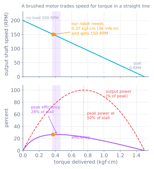
That is the whole selection process closing: a garden-variety yellow TT gearmotor is the right part for this robot, and now you know why rather than because it came in the box.
Why a quarter of stall, and not half
The advice you meet is “size for about a quarter of stall torque”. It is usually stated as a rule of thumb. It is not — it is where the efficiency peak sits, and you can derive it.
Current rises linearly with torque, from no-load current I₀ to stall current I_s, while speed falls linearly to zero. Output power is torque × speed and input power is voltage × current, so with x = T / T_stall and k = I₀ / (I_s − I₀):
η ∝ x(1 − x) / (x + k)Differentiate, set to zero, and the maximum is at:
x* = −k + √(k² + k)| No-load current as a fraction of stall | Efficiency peaks at |
|---|---|
| 0.10 | 24.0% of stall |
| 0.15 | 27.9% of stall |
| 0.20 | 30.9% of stall |
Hobby gearmotors live in that range, so “a quarter to a third of stall” is the answer for essentially all of them. Peak power, by contrast, is always at exactly 50% of stall — and that is a bad place to run. At half stall torque you are drawing roughly half stall current continuously, most of the extra is I²R heating in the windings, and a small motor has nowhere to put it. Motors sized for peak power get hot and stay hot.
The other half of the argument is headroom. Sitting at 25% of stall leaves a factor of four in reserve, which is what carries the robot over the threshold strip, out of the corner it wedged itself into, and up the ramp you did not design for. On a small robot that reserve is often unreachable anyway — friction runs out long before the motors do, so the force you can actually deliver is µ times the weight on the driven wheels rather than anything on the datasheet.
The gear ratio moves both numbers at once
This is the knob, and it is a see-saw, not a dial:
output torque  =  motor torque × ratio × efficiency
output speed   =  motor speed  ÷ ratio
Halve the ratio and you double the speed and halve the torque. There is no setting that gives you more of both, and no battery upgrade that substitutes for it — a higher voltage raises both no-load speed and stall torque, but it raises current and heat with them, and it does not change the shape of the trade.
On 65 mm wheels, driven at 6 V:
| Gearmotor | No-load output | Top speed | Suits |
|---|---|---|---|
| TT 1:48 | ~200 RPM | 0.68 m/s | General 2WD, line followers |
| N20 1:100 | ~200 RPM | 0.68 m/s | Same speed, far less backlash |
| N20 1:298 | ~65 RPM | 0.22 m/s | Careful, heavy, or climbing robots |
| N20 1:30 | ~600 RPM | 2.04 m/s | Light racing chassis only |
If the arithmetic gives you a speed you want and a torque you cannot reach, the fix is a higher ratio and a smaller wheel — both multiply torque at the ground.
The current your driver has to survive
Sizing torque is not the end of the job, because the number the driver must survive is not the running current. It is the stall current, and you hit stall every single time the robot starts from rest, plus every time a wheel jams against a wall.
A TT gearmotor at 6 V draws roughly 200 mA running and around 1 A stalled. Two of them is 2 A of worst case, on top of whatever the controller and sensors take.
- An L298N handles 2 A per channel, which covers it — but it burns about 2 V across its output stage as heat, so a 6 V pack delivers about 4 V to the motor and every number on the datasheet scales down with it.
- A TB6612FNG does the same job with MOSFETs at 1.2 A continuous and 3.2 A peak per channel, and keeps the volts a small pack cannot spare.
Size the battery pack for the stall case too. A pack that sags under 2 A will brown out the microcontroller mid-move, and the symptom looks exactly like a software crash.
Check these before you buy
- Which voltage is the datasheet quoting? The same motor at 3 V and 6 V has two entirely different lines. Match the number to your actual pack under load, not its label.
- Is that RPM before or after the gearbox? Output-shaft RPM is what you want. Motor-shaft RPM divided by the ratio is what you get.
- Does the shaft fit your wheels? A 3 mm D-shaft and a 4 mm hex are not interchangeable, and adapters add slop.
- How will you mount it? Bracket availability decides more hobby builds than torque does.
- Do you need to know how far it turned? Then buy the encoder version now. Retrofitting one is harder than it sounds.
When it goes wrong
| Symptom | Usually |
|---|---|
| Robot moves on the bench, stalls on carpet | Rolling resistance underestimated; measure C_rr with a spring scale |
| Fine at speed, sluggish from a standstill | Acceleration force left out of the budget |
| Motors get hot after a few minutes | Running near peak power (~50% of stall) rather than peak efficiency |
| One motor much slower than the other | Not the motor — driver voltage drop, or a wheel binding on its mount |
| Robot is uncontrollably fast at 20% PWM | Gear ratio too low for the wheel size; all your resolution is at the bottom |
| Board resets whenever the robot starts moving | Stall current sagging a shared supply; separate the motor rail |
| Torque figure looks 68× too good | kgf·cm read as N·m |
The point of doing this on paper is that all seven of those rows are cheaper to avoid than to diagnose. Once the motor is chosen, the next question is how to command it without asking for a step change it cannot deliver — that is motion profiling — and how much of the motion you commanded actually reaches the wheel, which is gearbox backlash.
Explore the graph
Part of these builds
Projects and learning paths that include this tutorial.
Further reading