
Tutorial · Intermediate · 22 min read
Camera Calibration and ArUco Pose with OpenCV
Calibrate a robot camera with OpenCV, measure reprojection error, detect ArUco markers, and estimate marker pose with correct units and coordinates.
A camera image reports pixels, but a robot needs rays and coordinates. Camera calibration estimates the intrinsics that map 3D camera-frame points to pixels and the distortion introduced by the lens. Once those values are known, a marker with known geometry can provide its position and orientation relative to the camera.
ArUco markers are square binary fiducials with an ID. Detecting the four corners identifies the marker in the image; pose estimation combines those pixel corners, the real marker size, and calibrated camera parameters.
Understand the calibration outputs
The camera matrix contains focal lengths and the optical centre:
[ fx   0  cx ]
[  0  fy  cy ]
[  0   0   1 ]
fx and fy are expressed in pixels. cx and cy locate the principal point. Distortion coefficients model effects such as radial barrel/pincushion distortion and tangential decentring.
These values belong to a camera, lens, focus setting, and image geometry. Changing resolution by cropping or rescaling may require adjusting intrinsics; changing focus or replacing the lens calls for recalibration.
Print and measure a calibration target
A chessboard is a practical first target because the internal corners are easy to define. Measure the square size accurately. Pose scale inherits this unit: object points in metres produce translations in metres; object points in millimetres produce millimetres.
Keep the target flat. A curled sheet violates the planar geometry assumed by the object points. Mount it on rigid material if accuracy matters.
Define the number of internal corners, not printed squares. A board with 10 by 7 squares has 9 by 6 internal corners. Mixing those counts makes detection fail even when the image looks clear.
Capture a useful image set
Collect at least ten successful views as a starting point, then add diversity rather than duplicates. Move the board around the entire image, tilt it in both axes, vary distance, and include corners near the image edges where distortion is strongest. Keep the pattern sharp and completely visible.
Twenty nearly identical front-facing frames provide less information than fewer well-distributed poses. Reject motion blur and frames where corner detection is uncertain. Use the same resolution and camera settings planned for operation.
For every accepted image, store the detected image corners and the corresponding planar object points (column × squareSize, row × squareSize, 0).
Calibrate with OpenCV
The essential Python flow is:
import cv2
import numpy as np

pattern = (9, 6)          # internal corners: columns, rows
square_size = 0.024       # metres

object_template = np.zeros((pattern[0] * pattern[1], 3), np.float32)
object_template[:, :2] = np.mgrid[0:pattern[0], 0:pattern[1]].T.reshape(-1, 2)
object_template *= square_size

object_points, image_points = [], []

for gray in calibration_images:
    found, corners = cv2.findChessboardCorners(gray, pattern)
    if not found:
        continue
    refined = cv2.cornerSubPix(
        gray, corners, (11, 11), (-1, -1),
        (cv2.TERM_CRITERIA_EPS + cv2.TERM_CRITERIA_MAX_ITER, 30, 0.001),
    )
    object_points.append(object_template.copy())
    image_points.append(refined)

rms, camera_matrix, distortion, rvecs, tvecs = cv2.calibrateCamera(
    object_points, image_points, gray.shape[::-1], None, None
)
Guard against too few accepted images before calling calibration. Save the matrix, distortion coefficients, image width/height, target definition, and calibration date together. A bare array file is easy to misuse later.
Validate more than the returned RMS value
The root-mean-square (RMS) reprojection error summarizes how far projected calibration points are from detected image points. Lower is generally better, but one number can hide bad regions or a weak image set.
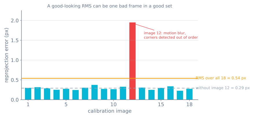
Calculate per-image reprojection error and inspect the worst views. Draw reprojected points over the images. Check straight architectural edges after undistortion, especially near corners. Then estimate the pose of a target at a known distance and compare translation with a physical measurement.
If one image dominates the error, inspect and remove it only for a defensible reason such as blur or incorrect corner order. Repeatedly deleting high-error frames until the number looks good can hide a poor model or target.
Detect an ArUco marker
Choose a predefined dictionary and generate markers from that same dictionary. Larger bit grids offer more IDs but each bit receives fewer pixels at a fixed image size. Print the marker with a quiet white border and measure the black-square side length used by the pose model.
dictionary = cv2.aruco.getPredefinedDictionary(cv2.aruco.DICT_4X4_50)
parameters = cv2.aruco.DetectorParameters()
detector = cv2.aruco.ArucoDetector(dictionary, parameters)

corners, ids, rejected = detector.detectMarkers(frame)
API construction differs across older OpenCV releases, so match the code to the installed version’s official documentation. The outputs should still provide four ordered image corners per detected marker.
Estimate pose with a known marker size
Define marker corners in its own coordinate frame and solve the perspective-n-point problem. For a marker side s, OpenCV’s square-specific solver expects a consistent corner order:
s = 0.080  # metres
object_corners = np.array([
    [-s/2,  s/2, 0],
    [ s/2,  s/2, 0],
    [ s/2, -s/2, 0],
    [-s/2, -s/2, 0],
], dtype=np.float32)

ok, rvec, tvec = cv2.solvePnP(
    object_corners,
    corners[0].reshape(4, 2),
    camera_matrix,
    distortion,
    flags=cv2.SOLVEPNP_IPPE_SQUARE,
)
tvec is the marker origin expressed in the camera frame and uses the same length unit as s. rvec is a Rodrigues rotation vector, not Euler angles. Use cv2.Rodrigues() to obtain a rotation matrix or transform it through the robot’s frame system.
Draw projected coordinate axes and verify them physically. A positive translation with believable magnitude is not enough if axes are mirrored or the wrong marker size was entered.
Make pose stable enough for a robot
Pose becomes noisy when the marker occupies few pixels, lies at a steep angle, is blurred, or approaches the image edge. Improve lighting and exposure, use a larger marker, move closer, or use a board of multiple markers when the application permits.
Filter only valid poses and retain timestamps. A low-pass filter reduces jitter but adds control lag. Reject sudden results using reprojection error, distance bounds, and motion limits rather than blindly averaging every detection.
The marker pose is relative to the camera. To command a robot arm or mobile base, transform it through the calibrated camera mount into base_link or the arm base. A millimetre/meter mismatch here creates a thousand-fold error.
Diagnose common failures
- Undistortion bends straight lines: calibration views lack coverage, the target was not flat, or image geometry changed.
- Distance scale is consistently wrong: square or marker size uses the wrong measurement or unit.
- Pose axes point the wrong way: object-corner order or frame convention is wrong.
- Marker ID flickers: the marker is too small, blurred, poorly printed, or from a different dictionary.
- Pose jumps near a front-facing view: planar pose ambiguity and weak pixel geometry need better viewpoints, tracking, or multi-marker constraints.
- Calibration works at one resolution only: intrinsics were reused after crop/resize without adjustment.
- Robot motion lags the marker: excessive smoothing or stale timestamps hide current geometry.
Use the Sensor Simulator to explore noise, bias, filtering, and latency. The Robot Arm Simulator shows how a target pose can still be unreachable after camera geometry is correct.
Explore the graph
Part of these builds
Projects and learning paths that include this tutorial.
Further reading