
Component · Chassis
2WD Robot Chassis
The 2WD chassis is the deck your motors, wheels, caster, and boards bolt onto. How to pick one, and why 2WD beats 4WD for a beginner robot.
What it is
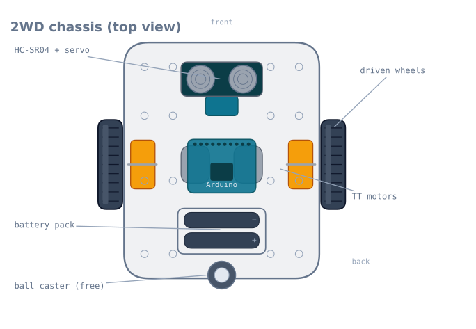
The chassis is the body of the robot—the flat deck that carries everything else. A 2WD (“two-wheel drive”) chassis holds two driven wheels, each on its own TT gearmotor, and a single free-rolling caster for balance. Add a battery, a driver board, and a controller, and the deck becomes a robot that can drive forward and turn.
It sounds like the boring part, but the chassis quietly decides how the whole robot behaves: where the weight sits, how it turns, and where the sensors can see from.
How it works
A 2WD base steers by differential drive: there is no steering wheel, so the robot turns by driving its two wheels at different speeds. Both wheels forward at the same speed drives straight; slow or reverse one wheel and the robot curves or spins on the spot. The free caster just slides along and keeps the deck level—it carries no drive and does no steering. The maths of turning wheel speeds into motion is covered in differential-drive odometry.
Because the two driven wheels sit on a shared axle line, the robot pivots around the centre point between them. Putting the caster at the back and the sensor at the front makes that pivot predictable.
When to use it
A 2WD chassis is the right base for essentially every first robot: line followers, obstacle-avoiders, and maze robots all start here. It keeps the mechanics trivial so you can spend your effort on the sensing and the control loop.
Choose something else when the robot needs to carry real weight, climb, or drive over rough ground—then a 4WD or tracked chassis with metal-gear motors earns its extra cost and complexity.
Choosing and mounting
- 2WD over 4WD to start. One caster avoids the wheel-scrub of four fixed wheels and makes turn-in-place steering clean.
- Keep weight over the driven wheels. Traction comes from load on the tyres; a nose-heavy robot spins its wheels. Mount the battery near the axle line.
- Leave the front bay clear. Reserve the front slot for the ultrasonic sensor and its servo, low and unobstructed, so nothing blocks the beam.
- Route cables away from the wheels. Tuck motor and sensor leads so they can’t foul a spinning tyre—a surprisingly common first-run failure.
The geometry that decides how your robot behaves
Three measurements on a chassis determine almost everything about how the finished robot drives. Measure yours and write them down — every piece of navigation code needs them.
| Measurement | Typical | What it controls |
|---|---|---|
| Wheelbase (track width, wheel centre to wheel centre) | 130–160 mm | How fast it turns for a given wheel-speed difference |
| Wheel diameter | 65 mm | Distance per encoder count, and top speed |
| Caster position (behind the axle) | 80–120 mm | Stability, and how much the caster scrubs in a turn |
The wheelbase is the one people never measure and always need:
turn rate (rad/s) = (v_right - v_left) / wheelbase
distance per pivot degree = pi x wheelbase / 360
For a 140 mm wheelbase, a 90° pivot means each wheel travels
pi × 140 / 4 = 110 mm in opposite directions. Get the wheelbase wrong by 10 mm and every
turn is off by 7% — which reads as a badly tuned controller and is actually a tape-measure
problem.
Measure to the tyre contact patch centre, not the outside of the wheels or the motor mounting holes. On a 65 mm wheel with a 25 mm wide tyre, that is a 25 mm difference between the outside-to-outside and centre-to-centre figures, and 25 mm on a 140 mm wheelbase is 18%.
Weight distribution
Traction is proportional to the load on the driven tyres, and a 2WD chassis distributes that load by where you bolt things down.
| Layout | Load on driven wheels | Result |
|---|---|---|
| Battery over the axle | ~85% | Best traction, clean pivots |
| Battery centred on the deck | ~65% | Adequate |
| Battery at the front, near the caster | ~40% | Wheels spin; the robot accelerates poorly |
| Battery behind the caster | Can lift the drive wheels | The robot pivots on the caster and goes nowhere |
The battery is usually the heaviest single item, often more than everything else combined, so where the battery sits is the weight distribution. Mount it over or slightly ahead of the axle line — ahead, because the caster is behind, and you want the deck to rest on the caster rather than teeter.
There is one exception worth knowing. A robot that has to push — a mini sumo, for instance — wants as much weight as possible on the drive wheels, right up to the point where the caster barely touches. A robot that has to follow a line precisely wants the opposite: stable, predictable, with the sensor array held at a constant height, which a teetering chassis will not do.
Where to mount the sensors
| Sensor | Position | Why |
|---|---|---|
| IR reflectance array | Front, 3–8 mm above the floor, ahead of the axle | Height decides contrast; forward position gives the controller lead time |
| Ultrasonic | Front, as high as practical, unobstructed | The cone will pick up the deck itself if mounted low |
| Bump switches | Behind a wrapped shell, left and right | Two, so the robot knows which way to turn |
| IMU | Near the pivot centre, rigid, level | Away from the pivot it reads centripetal acceleration as tilt |
| Battery | Over the axle | Traction — see above |
The IMU placement is the subtle one. An accelerometer mounted well forward of the pivot centre experiences centripetal acceleration during a turn, and a complementary filter will interpret that as a tilt. Mounting it over the axle line minimises the effect.
The ultrasonic height matters more than expected: with a 15° half-angle cone, a sensor mounted 40 mm above the deck and looking forward will start seeing the deck itself at around 150 mm out — reporting a permanent obstacle that is your own robot.
The caster problem
The free-rolling caster is the cheapest part on the chassis and the most common source of mysterious steering error.
A swivel caster has to rotate to face the new direction whenever the robot changes direction, and while it is doing so it drags sideways. That drag is a force on one corner of the robot, which pulls it off course — and it happens on every direction change, so the error is systematic rather than random. This shows up as a robot that tracks well in a straight line and consistently misses turns.
A ball caster has no such swivel and simply rolls in any direction. It is worse on carpet, where the ball digs in, and better on smooth floors.
| Caster type | Smooth floor | Carpet | Direction changes |
|---|---|---|---|
| Ball caster | Excellent | Poor — digs in | No scrub |
| Swivel caster | Good | Good | Scrubs on every change |
| Skid (a smooth dome) | Good | Fair | No scrub, but adds friction |
| Second caster (4-point) | Rocks unless perfectly flat | Poor | Avoid on a 2WD deck |
Two practical notes. One caster, not two — three contact points define a plane and are always stable, while four points on a rigid deck will rock. And if the robot must reverse, a swivel caster must flip 180° first, which briefly steers the robot; robots that back away from obstacles reliably veer for this reason alone.
Assembly gotchas
These are the ones that cost a first build the most time.
Mount the motors before anything else. They are the hardest to reach once the deck is populated, and the mounting screws on most kits are captive between the motor and the deck.
Check the wheels are square. A wheel pushed on crooked — very easy with the double-D bore — wobbles, which changes the effective rolling radius through each rotation. The robot then weaves at a frequency tied to wheel rotation, which looks like an oscillating controller.
Route cables away from the wheels first, not last. Cable ties through the deck’s mounting grid, before the deck is crowded. A motor lead that reaches a spinning tyre gets stripped in seconds, and it is one of the most common first-run failures.
Leave the acrylic’s protective film on until assembly is finished. It scratches easily, and the film also stops the drill from chipping the edges of the mounting holes.
Do not overtighten acrylic. It cracks around holes under load, particularly at the motor mounts where the vibration is. Nylon washers and finger-tight plus a quarter turn.
Troubleshooting
| Symptom | Likely cause | Fix |
|---|---|---|
| Wheels spin, robot barely moves | Weight not over the driven wheels | Move the battery back over the axle |
| Robot veers consistently | Motor mismatch, or a crooked wheel | Trim in software; check the wheels are square |
| Weaves at a steady frequency | A wobbling wheel | Reseat it on the double-D shaft |
| Turns are consistently short or long | Wheelbase measured wrong | Measure to the contact patch centres |
| Tracks straight, misses turns | Swivel caster scrubbing | Ball caster, or account for it |
| Veers when reversing | Caster flipping 180° | Expected with a swivel; pause briefly before reversing |
| Motor lead severed | Cable routed near a tyre | Tie cables through the deck grid, away from the wheels |
| Chassis rocks | Two casters, or an uneven deck | One caster only |
| Sensor readings change over bumps | Sensor bracket flexing | Mount rigidly; flex changes the ride height |
2WD or something else?
| Layout | Turning | Traction | Complexity | Best for |
|---|---|---|---|---|
| 2WD + caster | Pivots on the spot cleanly | Two wheels’ worth | Lowest | Line followers, maze robots, first builds |
| 4WD (four fixed wheels) | Scrubs badly in a turn | Best | Low mechanically, harder to control | Rough ground, pushing |
| Tracked | Scrubs constantly | Excellent | Medium | Obstacles, loose surfaces |
| Ackermann (car steering) | Cannot pivot; needs a turning circle | Two wheels’ worth | Highest | Realistic vehicle dynamics |
| Omni / mecanum | Moves sideways without turning | Poor — 71% of a plain wheel | High: four motors, four encoders | Holonomic motion in flat, clean spaces |
Start with 2WD, and the reason is odometry rather than mechanics. A two-wheel differential drive with one free caster has a clean kinematic model: the wheels roll without scrubbing, so encoder counts convert to a pose with only the errors you expect. A 4WD chassis with four fixed wheels must scrub in every turn, because the wheels on each side follow different arcs while being forced to rotate at the same rate — so its odometry is wrong from the first turn, in a way that is hard to model.
That makes 2WD not merely the simplest starting point but the correct one for learning: it is the layout on which differential-drive odometry actually works.
Explore the graph
Used in these builds
Projects, learning paths, and simulators that include the 2WD Robot Chassis.
- ProjectBuild a GPS Waypoint Rover That Drives Itself
- ProjectBuild a Line Follower Robot With an 8051 Microcontroller
- ProjectBuild a Line Follower Robot: From Simulator to Real Track
- ProjectBuild a Line Maze Solver Robot With LSRB Route Memory
- ProjectBuild a Micromouse: A Flood-Fill Maze-Solving Robot
- ProjectBuild a Mini Sumo Robot: Grip, Wedge and Edge Sense
- ProjectBuild a Phone-Controlled Robot Car Over Bluetooth or Wi-Fi
- ProjectBuild a Room Coverage Robot That Sweeps a Floor
- ProjectBuild a ROS 2 Robot That Sees and Drives to a Marker
- ProjectBuild a Self-Balancing Robot With an MPU6050 and PID
- ProjectBuild an Obstacle-Avoiding Robot: Sense, Scan, and Steer
Compare
Alternatives
Questions
2WD Robot Chassis FAQ
What is a 2WD robot chassis?
A 2WD robot chassis is a flat deck with mounts for two driven wheels and one free-rolling caster, plus room for the motors, battery, and boards. It is the mechanical body of a beginner robot car—everything else bolts onto it.
Is 2WD or 4WD better for a beginner robot?
2WD is better to start. It is cheaper, simpler to wire, and turns in place using differential drive with a single caster for balance. A 4WD chassis has more traction but its fixed wheels scrub sideways in every turn, which complicates steering and drains the battery.
What wheels does a 2WD chassis use?
Almost always 65 mm rubber wheels with a double-D bore that presses onto a TT gearmotor's double-D shaft. The rubber tyre gives grip; the flat on the bore stops the wheel slipping on the shaft.
Where do the sensors go on a 2WD chassis?
On the front edge. Most decks have a slot or bay at the front for an ultrasonic or IR sensor, low and facing forward. For an obstacle-avoiding robot you mount the HC-SR04 there on a small servo so it can scan left and right.
Further reading