
Tutorial · Beginner · 18 min read
Control DC Motors with PWM and an H-Bridge
Learn to control a brushed DC motor with PWM and an H-bridge, including direction, braking, current limits, wiring, and safe driver selection.
A microcontroller pin can describe how a motor should move, but it cannot safely supply the motor current. A brushed direct-current (DC) motor may draw several times its normal current while starting or stalled. An H-bridge motor driver sits between the controller and motor, switches that current from a separate supply, and lets the controller choose speed and direction.
This tutorial builds the motor stage used by line followers, maze robots, and small obstacle-avoidance platforms. The exact pin names vary by driver, but the electrical decisions stay the same.
Understand what the H-bridge changes
A DC motor reverses when the current through it reverses. An H-bridge uses four electronic switches around the motor. One diagonal pair drives current forward; the other drives it backward. Driver boards expose that switching through logic pins such as IN1 and IN2:
| IN1 | IN2 | Motor state |
|---|---|---|
| Low | Low | Coast or brake, depending on the driver |
| High | Low | Forward |
| Low | High | Reverse |
| High | High | Brake or coast, depending on the driver |
Never assume what both-low and both-high mean. Read the truth table for the specific driver. Some chips also have an ENABLE, STANDBY, or SLEEP pin that must be asserted before the outputs work.
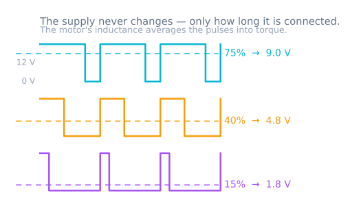
Pulse-width modulation (PWM) controls the average voltage by switching the drive rapidly on and off. A 25% duty cycle is on for one quarter of each period; it does not guarantee one quarter of the shaft speed because the result also depends on load, supply voltage, friction, and motor back electromotive force.
Choose the driver from current, not motor size
Find the motor’s rated voltage, no-load current, and stall current. Stall current is the important driver-sizing value because it is what the motor asks for when the shaft cannot turn. If the data sheet is unavailable, measure winding resistance with the motor disconnected and estimate stall current = supply voltage / winding resistance. Meter-lead resistance makes this only an estimate.
Choose a driver whose motor-voltage range includes the supply and whose peak current can survive startup. Then check continuous current and thermal conditions. A board advertised with a large peak number may handle it only briefly or with substantial cooling.
Also account for voltage drop. Older bipolar-transistor drivers can lose significant voltage inside the bridge; modern MOSFET drivers usually waste less power. For a battery robot, that difference affects torque and runtime.
Wire one motor safely
Use this order before applying power:
- Connect the motor supply to the driver’s motor-power input and ground.
- Connect the motor to the two driver outputs, not to a microcontroller pin.
- Connect controller ground to driver ground so the logic signals share a reference.
- Connect
IN1,IN2, and any enable pin to suitable digital pins. - Keep motor wiring short and route it away from analog sensor leads.
- Confirm the driver’s logic-voltage requirements before connecting a 3.3 V ESP32 or Raspberry Pi.
Use a fuse or current-limited bench supply during first power-up. Add local supply decoupling as the driver data sheet recommends. Never power a loaded motor through the Arduino’s 5 V regulator or USB connector — that is the brown-out that reads as a software crash.
Write one small motor function
The cleanest interface accepts a signed command: positive is forward, negative is reverse, and zero is stopped. On an Arduino-style board, a minimal implementation looks like this:
const int IN1 = 7;
const int IN2 = 8;
const int PWM_PIN = 5;

void setMotor(int command) {
  command = constrain(command, -255, 255);
  digitalWrite(IN1, command >= 0 ? HIGH : LOW);
  digitalWrite(IN2, command >= 0 ? LOW : HIGH);
  analogWrite(PWM_PIN, abs(command));
}
This example assumes a driver with a separate PWM/enable input. A two-input driver may expect PWM on one input while the other holds the direction state. Follow its truth table rather than copying pin logic blindly.
When reversing, command zero briefly before changing direction. An instant full-speed reversal produces a large current transient and mechanical shock. A simple ramp also improves traction:
for (int command = 0; command <= 180; command += 5) {
  setMotor(command);
  delay(15);
}
In a real control loop, make that ramp time-based instead of using blocking delay() calls.
Test direction, speed, coast, and brake
Lift the wheels clear of the table for the first test. Begin with a low duty cycle, confirm the commanded direction, then increase it gradually. Record the lowest command that reliably starts the motor. Static friction creates a dead zone, so commands below that threshold may hum without moving.
Next, compare stopping modes. Coasting disconnects or releases the bridge and lets momentum slow the motor. Dynamic braking shorts the motor terminals through the bridge so the spinning motor dissipates energy and stops faster. Braking produces more electrical and mechanical stress, so use it deliberately.
Finally, place the robot on the floor and repeat. A motor that spins unloaded may brown out the controller under real load. Watch the supply voltage during startup and verify that the driver is not overheating.
Diagnose the common failures
- The controller resets when the motor starts: the supply sags or motor noise reaches the logic rail. Use adequate battery current, local decoupling, clean grounding, and separate regulation for logic where appropriate.
- The motor only runs one way: verify both logic inputs at the driver and confirm that standby or enable is asserted.
- Speed barely changes with PWM: check that the chosen pin actually supports PWM and that the driver accepts PWM on that input.
- The driver becomes hot: compare load and stall current with the continuous rating, check voltage drop, and inspect for a mechanically stalled drivetrain.
- Sensors become noisy: separate motor and sensor wiring, add the suppression recommended by the motor/driver manufacturer, and filter measurements only after fixing the electrical path.
Once one motor works predictably, duplicate the channel for a differential-drive robot. The Line Follower Simulator demonstrates how two signed wheel commands become steering, while the PID Controller Simulator shows how feedback can regulate speed instead of relying on raw duty cycle.
Keep the hardware calibration knobs
Two nominally identical motors rarely produce identical speed. Preserve a per-wheel scale factor and the minimum-start command in software. Measure rather than hiding the mismatch with a fixed unexplained offset. Later, quadrature encoders can close the loop and correct speed as battery voltage and load change.
Explore the graph
Part of these builds
Projects and learning paths that include this tutorial.
- ProjectBuild a Line Follower Robot With an 8051 Microcontroller
- ProjectBuild a Line Follower Robot: From Simulator to Real Track
- ProjectBuild a Phone-Controlled Robot Car Over Bluetooth or Wi-Fi
- ProjectBuild an Obstacle-Avoiding Robot: Sense, Scan, and Steer
- Learning pathMotor Control for Robots: A Learning Roadmap
Further reading