
Component · Actuator
DC Gearmotor (TT Motor)
The yellow TT gearmotor is the drive motor behind most beginner robot cars. How its gearbox works, its real voltage and speed, and why it needs a driver.
What it is
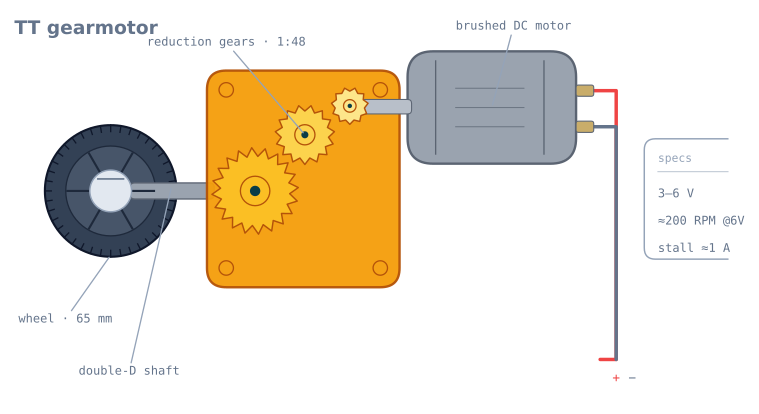
The TT gearmotor is the yellow-and-blue motor at the bottom of nearly every beginner robot car. It is a small brushed DC motor bolted to a plastic reduction gearbox, with a double-D output shaft that presses straight into a matching wheel. Buy two, add a chassis and a caster, and you have a robot that can drive and turn—which is why it is the drive motor behind the first line follower or obstacle-avoider most people build.
On its own a bare DC motor spins far too fast and far too weakly to move anything. The gearbox is what makes it useful: it turns that fast, feeble spin into the slow, strong turn a wheel needs.
How it works
Two things happen inside the yellow case:
- The motor turns electrical energy into rotation. Put voltage across its two terminals and it spins; reverse the polarity and it spins the other way. More voltage means more speed.
- The gearbox reduces that speed. A ~1:48 gear train means the wheel turns once for roughly every 48 turns of the motor. You lose speed and gain torque in the same ratio, which is the trade you want—a wheel needs force, not a blur. Whether this ratio is the right one for your robot is arithmetic you can do before you buy: see choosing a DC gearmotor.
To control it you do two things at once: set direction by choosing which terminal is positive (the H-bridge does this), and set speed with PWM—switching the supply on and off fast so the motor sees an average voltage. Learn that pairing in control DC motors with PWM and an H-bridge.
When to use it
Reach for a TT motor for any light, low-speed wheeled robot: line followers, obstacle-avoiders, maze robots, a first differential-drive base. It is cheap, forgiving, and every beginner tutorial targets it.
Step up when you need more: add wheel encoders when you want to measure distance and speed for odometry, or move to metal-gear motors when the robot gets heavy or needs to climb. The plastic gears strip under abuse.
Wiring and gotchas
- Never wire it straight to a logic pin. Stall current is around 1 A. Drive it through an L298N or similar H-bridge, powered from the battery—not from the Arduino’s 5 V.
- Two motors won’t match. Identical PWM rarely drives perfectly straight; trim one motor in software, or close a speed loop with encoders.
- Mind inrush and back-EMF. Motors dip the supply when they start and kick voltage back when they stop. Keep motor power and logic power on separate rails sharing a common ground—see powering a robot.
- Match the wheel to the shaft. The double-D shaft only seats correctly in a matching double-D wheel bore; a round hole will slip.
The four numbers on a motor datasheet
Every brushed DC motor is characterised by four figures, and they are not independent — the whole curve follows from two of them.
| Number | TT motor at 6 V | What it means |
|---|---|---|
| No-load speed | ~200 RPM | The fastest it will ever turn, with nothing attached |
| No-load current | ~150 mA | What it draws spinning freely — mostly gearbox friction |
| Stall torque | ~0.8 kg·cm | The most force it can produce, at zero speed |
| Stall current | ~1 A | What it draws when held still. The number your driver must survive |
A brushed DC motor’s torque falls linearly with speed, from stall torque at zero RPM to zero torque at no-load speed. Its current does the same thing in reverse. That gives three consequences worth knowing:
Maximum power is at half speed. Power is torque × speed, and the product of two lines peaks in the middle. A TT motor at 6 V produces its most power around 100 RPM.
Maximum efficiency is at roughly a quarter of stall torque, well above the power peak. This is the point you want to design a robot to run at — not the power peak, and certainly not near stall.
Stall current is the design constraint, not running current. A motor drawing 150 mA happily will pull 1 A the instant a wheel jams against a wall, and two of them stalling together is 2 A. Your driver and your battery must both survive that, because on a robot it happens constantly.
Sizing one for your robot
The arithmetic takes five minutes and settles most “my robot is too slow” questions before they happen.
Speed. Wheel circumference × RPM ÷ 60 gives you metres per second:
65 mm wheel -> circumference = pi x 0.065 = 0.204 m
200 RPM     -> 200 / 60 = 3.33 rev/s
speed       = 0.204 x 3.33 = 0.68 m/s
That is walking pace, which is about right for a line follower and rather fast for a maze robot that must stop at junctions.
Torque. To accelerate a robot of mass m at rate a, each of n driven wheels needs:
torque per wheel = m x a x r / nFor a 500 g robot accelerating at 0.5 m/s² on 65 mm wheels (r = 0.0325 m) with two driven wheels:
= 0.5 x 0.5 x 0.0325 / 2 = 0.004 N.m = 0.041 kg.cmAgainst a stall torque of 0.8 kg·cm that is a factor of nearly twenty in hand, which is why TT motors work fine for light robots and why nobody usually has to do this calculation. Do it when the robot gets heavy, or has to climb.
Then check the floor. Motor torque is only one ceiling; friction is the other. A light robot on a smooth floor typically reaches its traction limit at around a quarter of stall torque — so most of a motor’s capability cannot reach the ground at all. The pushing force and traction tutorial works through which limit you actually hit.
Why your robot does not drive straight
Two TT motors given identical PWM will not drive straight, and this surprises people more than it should. The causes, roughly in order of size:
| Cause | Typical size | Fixable by |
|---|---|---|
| Gearbox friction differences | 5–15% speed difference | Software trim, or a speed loop |
| Motor winding variation | A few percent | Same |
| Wheel diameter variation | 1–2% | Measure and correct in odometry |
| Uneven weight distribution | Varies | Move the battery |
| Different starting thresholds | One wheel starts at 25% duty, the other at 32% | Measure both; this one dominates at low speed |
The last row is the one that catches people, because it only appears at low speed. A robot that tracks well at full tilt and veers hard when creeping is showing you two different stiction thresholds, not a steering bug.
There are two real fixes. The software trim is a per-motor multiplier you find empirically — drive forward, measure the drift over 2 m, adjust, repeat. It is quick and it only holds for the battery voltage and surface you tuned it on. The proper fix is encoders and a speed loop, which corrects continuously and does not care about the battery.
The deadband, and why it matters
Below a certain duty cycle the motor does not turn at all — static friction in the brushes and the gear train has to be overcome first. On a TT motor this is typically 20–35% duty, and it differs between two motors from the same bag.
Measure yours:
// Ramp up slowly and note where each wheel starts.
for (int duty = 0; duty <= 255; duty += 5) {
  analogWrite(ENA, duty);
  Serial.println(duty);
  delay(500);                 // long enough to see it start
}
Then compensate, so that a small command produces a small motion rather than nothing:
const int DEADBAND_A = 65;    // measured, out of 255

int applyDeadband(int speed) {
  if (speed == 0) return 0;
  int sign = (speed > 0) ? 1 : -1;
  return sign * map(abs(speed), 1, 255, DEADBAND_A, 255);
}
Without this, the bottom quarter of your control range does nothing at all — which makes a PID loop behave very strangely near its setpoint, since small corrections have literally no effect until the accumulated integral term crosses the threshold and the robot lurches.
Troubleshooting
| Symptom | Likely cause | Fix |
|---|---|---|
| Board resets when motors start | Motor current through the controller | Separate battery; share only ground |
| Motor hums but does not turn | Below the deadband, or gearbox jammed | Raise the duty; check for a stripped gear |
| Robot veers at low speed only | Different stiction thresholds | Measure and compensate each motor separately |
| Robot veers at all speeds | Trim, or wheel diameter mismatch | Software trim, then measure the wheels |
| Gets slower as the run goes on | Battery sagging | Speed scales with voltage; close a speed loop or use a fresh pack |
| Grinding noise, then free spinning | Stripped plastic gear | These strip under shock; metal-gear motor if it recurs |
| Wheel wobbles on the shaft | Round bore on a double-D shaft | Use a matching double-D wheel |
| One motor much weaker | Brush wear, or a partially stripped gear | Swap the motors to confirm which side follows the fault |
| Both motors stutter together | Supply cannot deliver stall current | Bigger pack; check internal resistance |
TT motor or something else?
| Motor | Typical spec | Choose it when |
|---|---|---|
| TT gearmotor | 3–6 V, ~200 RPM, plastic gears, ~$2 | Learning, light robots, anything on a flat floor |
| TT with encoder | Same, plus a magnetic encoder | You want odometry — buy this instead, retrofitting is painful |
| N20 metal gearmotor | 6–12 V, many ratios, metal gears, ~$8 | Small robots needing precision or durability |
| 25GA-370 | 12 V, high torque, metal gears | Heavier robots, climbing, outdoor rovers |
| Continuous-rotation servo | 4.8–6 V, built-in driver | You want a wheel with no separate motor driver |
The one piece of buying advice that saves the most rework: if you think you might want encoders, buy motors with encoders now. Retrofitting means dismantling the drivetrain, and the price difference is a couple of dollars per motor. Almost every project that starts as a line follower and grows into a maze solver hits this.
Explore the graph
Used in these builds
Projects, learning paths, and simulators that include the DC Gearmotor (TT Motor).
- ProjectBuild a Line Follower Robot With an 8051 Microcontroller
- ProjectBuild a Line Follower Robot: From Simulator to Real Track
- ProjectBuild a Line Maze Solver Robot With LSRB Route Memory
- ProjectBuild a Phone-Controlled Robot Car Over Bluetooth or Wi-Fi
- ProjectBuild an Obstacle-Avoiding Robot: Sense, Scan, and Steer
- Learning pathMotor Control for Robots: A Learning Roadmap
Compare
Alternatives
Questions
DC Gearmotor (TT Motor) FAQ
What is a TT gear motor?
A TT gear motor is a low-cost brushed DC motor with a plastic reduction gearbox and a double-D output shaft that presses into a standard robot-car wheel. It is the default drive motor for the first wheeled robot most people build, because two of them plus a caster make a complete 2WD base.
What voltage does a TT motor need?
A TT motor runs on 3 to 6 volts. Most robot cars power it from a 4×AA (6 V) or 2×18650 (7.4 V) pack through a motor driver. It will spin at 3 V but with little torque; 6 V is the usual sweet spot for a light chassis.
Can an Arduino drive a TT motor directly?
No. A TT motor draws around 150 mA running and close to 1 A when stalled—far more than an Arduino pin can supply, and the back-EMF can damage the pin. Always drive it through an H-bridge such as the L298N, and control speed with PWM into the driver.
How fast does a TT gear motor spin?
About 200 RPM with no load at 6 V. Under the weight of a chassis it turns slower, which is exactly what the 1:48 gearbox is for—it trades the motor's high RPM for the torque needed to actually move the robot.
Why do my two TT motors make the robot veer instead of driving straight?
Cheap TT motors are never perfectly matched, so identical PWM gives slightly different speeds. Correct it in software by trimming one motor's PWM, or add wheel encoders and close a speed loop. This is also why obstacle and line-following robots steer by setting the two wheel speeds independently.
Further reading