
Component · Sensor
Lever Microswitch
A lever microswitch is the contact sensor behind a robot bumper. How to wire it fail-safe, why one press produces nine edges, and what the lever arm is for.
What it is
A lever microswitch — a miniature snap-action switch — is a mechanical contact in a small plastic body with a metal lever sticking out of it. Push the lever and an internal spring snaps the contact across; release it and the spring snaps it back. It is one of the oldest components in this library and, on a robot, one of the most useful.
What makes it a robotics part is the snap action. The contact does not close gradually as you press; it jumps, at a repeatable point, with an audible click. That gives you a definite yes-or-no answer from a mechanism that is being shoved by a moving robot, which is exactly the situation where a gradual sensor gives you nonsense.
How it works
Three terminals: COM (common), NO (normally open) and NC (normally closed). Unpressed, COM is connected to NC. Pressed, it snaps across to NO. You use two of the three and ignore the other.
For a robot bumper, wire COM to ground and NO to the input pin, with the pin’s internal pull-up on:
pinMode(BUMP_L, INPUT_PULLUP);              // idle HIGH
bool pressed = digitalRead(BUMP_L) == LOW;  // LOW means the bumper moved
That arrangement fails safe: a broken bumper lead reads HIGH, which is not pressed. Wire it the other way and a snapped wire convinces the robot it is permanently colliding. For an emergency stop, use NC instead — there, a broken wire should stop the machine.
The lever trades force for travel. The bare plunger wants around 1 N over roughly 1 mm; a lever arm multiplies the movement so a bumper shell can travel 3–5 mm and trigger with a much lighter push. A roller on the end reduces friction where something slides across it rather than pressing straight in.
When to use it
Use one wherever the robot needs to know it has already made contact: bumpers, end stops on an arm or a slide, a lid or drawer sensor, or a docking detector. It is the sensing of last resort, and that is a compliment — it catches the black chair leg, the pane of glass, and the obstacle at the wrong height that every optical and acoustic sensor misses.
It is also the only sensing a random-bounce coverage robot needs. Two of these and a random number generator will cover a whole room, which is a remarkable amount of behaviour for two moving parts.
Look elsewhere when you need to avoid the collision rather than detect it — that is what an ultrasonic or time-of-flight sensor is for. Use both: the range finder avoids most obstacles, the switch catches the ones it cannot see.
Common gotchas
- One press is nine edges. Debounce it, and never attach an interrupt that counts — only one that sets a flag or captures a timestamp.
- The switch body is not a structural part. Give the bumper shell a hard stop that takes the impact. Switch bodies crack; that is what kills them long before the contacts wear out.
- Its own spring will not return your bumper. A microswitch pushes back with 50–100 g. Use rubber bands or light compression springs for the return and let the switch only sense.
- A flat bumper misses glancing hits. Wrap the shell round to at least 45° each side, with a switch behind each half so the code knows which way to turn.
- Long leads pick up motor noise. Keep the run short, twist the pair, and rely on the pull-up’s low-impedance path when closed.
- Contact ratings are for mains, not logic. A switch rated 5 A at 125 V AC is being asked to pass microamps here; the rating tells you nothing useful about its life in this job. Pre-travel and operating force do.
Wiring
Two of the three terminals, and which two decides how the robot fails.
| Use | COM to | Signal from | Idle state | Broken wire reads as |
|---|---|---|---|---|
| Bumper | GND | NO, pin INPUT_PULLUP |
HIGH | Not pressed — safe |
| Emergency stop | GND | NC, pin INPUT_PULLUP |
LOW | Pressed — safe |
| Either, external pull-up | GND | NO or NC, 10 kΩ to VCC | — | Same as above |
The distinction matters. A bumper wired to NO fails safe by reading “no collision”, which is right — a robot with a broken bumper lead should keep driving, not freeze. An emergency stop wired to NC fails safe by reading “stopped”, which is also right, for the opposite reason.
Use the internal pull-up. It costs nothing, needs no components, and gives a defined idle
state. A pin left as a bare INPUT with a switch on it floats when the switch is open, and
floating pins read whatever electrical noise is nearby — which on a robot full of motors is a
lot.
Debouncing, done properly
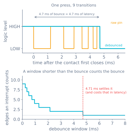
A single press produces around nine transitions over roughly 4.7 ms as the contacts snap and rebound. Software that reads the pin naively sees nine presses.
const int BUMP_L = 2, BUMP_R = 3;
const unsigned long DEBOUNCE_MS = 8;      // longer than the ~5 ms bounce

struct Bumper {
  uint8_t pin;
  bool stable;            // the debounced state
  bool lastRead;
  unsigned long changedAt;
};

Bumper left  = {BUMP_L, true, true, 0};
Bumper right = {BUMP_R, true, true, 0};

// Returns true on the frame the bumper newly closes.
bool update(Bumper &b) {
  bool now = digitalRead(b.pin);          // HIGH = open, with INPUT_PULLUP
  if (now != b.lastRead) {
    b.lastRead = now;
    b.changedAt = millis();               // restart the timer on any edge
    return false;
  }
  if (millis() - b.changedAt >= DEBOUNCE_MS && b.stable != now) {
    b.stable = now;
    return (now == LOW);                  // newly pressed
  }
  return false;
}

void setup() {
  pinMode(BUMP_L, INPUT_PULLUP);
  pinMode(BUMP_R, INPUT_PULLUP);
}

void loop() {
  if (update(left))  { backUp(); turnRight(); }
  if (update(right)) { backUp(); turnLeft(); }
}
The important structural detail is that the timer restarts on every edge, rather than sampling once and waiting. A fixed sample-and-wait can land inside the bounce and latch the wrong value; restarting the window means the state is only accepted once the pin has been quiet for the full period.
Why not an interrupt
Interrupts on a bump switch are a trap, and specifically:
- Never attach an interrupt that counts. Nine edges become nine counts, and a debounce
inside an ISR needs
millis(), which does not advance inside an ISR on an AVR. - A flag-setting interrupt is fine, if the debounce happens in the main loop. But polling a switch at 100 Hz costs nothing, and a robot’s loop is already running.
- Reserve D2 and D3 for encoders on an Uno. They are the only two external-interrupt pins, and encoders genuinely need them. A bumper does not.
The one case that justifies an interrupt is a hard emergency stop that must cut the motors even if the main loop has hung — and that is better solved by wiring the switch into the motor driver’s enable line, so it works with no software at all.
Mounting: the part that actually decides whether it works
Everything above is a solved problem. The mechanical design is where bumpers succeed or fail.
The shell takes the impact, not the switch. A microswitch body is thin plastic and cracks under a direct hit. Build a bumper shell that pivots or slides, give it a hard stop that takes the force, and let the switch sense a small movement near the end of that travel.
Wrap the shell. A flat front bumper misses everything hit at an angle — and a robot navigating by ranging sensors mostly hits things at an angle, because straight-on obstacles were already detected. Wrap to at least 45° each side.
Two switches, not one. Left and right, behind the two halves of the shell. One switch tells you that you hit something; two tell you which way to turn. The difference in behaviour is dramatic and the extra cost is about twenty cents.
| Switches | What the robot learns | Behaviour possible |
|---|---|---|
| 1, centre | Something was hit | Back up, turn a random direction |
| 2, left and right | Which side was hit | Back up, turn away from the contact |
| 3, adding a rear switch | Also that it reversed into something | Escape from being wedged |
Return the bumper with its own spring. A microswitch’s internal spring pushes back with only 50–100 g, which is not enough to reliably reset a shell with friction in its pivot. Use rubber bands or light compression springs, and let the switch do nothing but sense.
Set the pre-travel so the shell moves before the switch bottoms out. The switch operates after 1–3 mm and has a little over-travel beyond that; the shell’s hard stop must arrive within the over-travel, or the impact is taken by the switch’s internal mechanism.
Choosing one
| Lever type | Operating force | Best for |
|---|---|---|
| No lever (bare plunger) | ~1 N over ~1 mm | End stops where the mechanism is precise |
| Short straight lever | 0.5–0.8 N | General bumpers |
| Long straight lever | 0.2–0.5 N | Light bumper shells, delicate contact |
| Roller lever | 0.5–1 N | Anything that slides across rather than pressing in |
| Simulated roller (bent) | 0.5–1 N | Cheaper alternative to a roller |
The contact rating is irrelevant here. A switch rated 5 A at 125 V AC is being asked to pass a few microamps into a pull-up. What matters is the mechanical specification: operating force, pre-travel, and rated mechanical life (10⁵–10⁷ operations). A robot bumping a hundred times per run reaches 10⁵ operations after a thousand runs, so mechanical life is effectively unlimited — the switch will die from a cracked body long first.
Troubleshooting
| Symptom | Likely cause | Fix |
|---|---|---|
| One press triggers several times | No debounce | Use the pattern above with an 8 ms window |
| Reads pressed constantly | Wired to NC instead of NO | Swap to the NO terminal |
| Reads randomly with nothing touching | Pin floating | INPUT_PULLUP, or an external 10 kΩ |
| False triggers when motors run | Long unshielded leads picking up noise | Shorten and twist the pair; add a 100 nF cap across the pin |
| Bumper does not spring back | Relying on the switch’s own spring | Add rubber bands or a return spring |
| Switch cracked after a few collisions | Impact going through the switch body | Add a hard stop the shell hits first |
| Misses angled collisions | Flat bumper | Wrap the shell to 45° each side |
| Robot backs up but hits the same thing | One switch, no direction information | Two switches, and turn away from the one that fired |
| Works on the bench, not on the robot | Bumper geometry, not electronics | Push the shell by hand at several angles and watch the pin |
Why this cheap part earns its place
Every other sensor on a robot has surfaces it cannot see. An ultrasonic sensor is blind to curtains and to walls met at a steep angle. A VL53L0X is blind to black matte surfaces, mirrors, and anything in bright sunlight. A camera needs light.
A microswitch has no such list. If something is touching the bumper, the switch closes. That makes it the sensing of last resort, and on a robot that has to survive unattended it is the cheapest reliability available — two switches, two pins, and about forty cents.
It is also, remarkably, sufficient on its own. A robot with two bump switches and a random turn on contact will cover an entire room given enough time — which is exactly how the first generation of robot vacuums worked, and it is worth understanding before reaching for anything more sophisticated.
Explore the graph
Used in these builds
Projects, learning paths, and simulators that include the Lever Microswitch.
- ProjectBuild a Pen Plotter: Two Stepper Axes That Arrive
- ProjectBuild a Pick-and-Place Robot That Knows It Missed
- ProjectBuild a Room Coverage Robot That Sweeps a Floor
- Learning pathGrasping and End Effectors: Actually Pick It Up
- Learning pathPrecision Motion With Steppers: A Learning Roadmap
- Learning pathReactive Navigation: Teach a Robot to Avoid Obstacles
Questions
Lever Microswitch FAQ
What is a lever microswitch used for on a robot?
It is the sensor behind a bumper. A sprung shell across the front of the robot presses the switch when the robot makes contact, giving the code one unambiguous bit — I have hit something — that no optical or acoustic sensor can supply as reliably. It is what lets a robot detect a black chair leg, a pane of glass, or an obstacle at the wrong height for its range finder.
Should the switch be wired normally open or normally closed?
Normally open to ground with the pin pulled up, for a bumper. That way a broken wire reads as not pressed, so a snapped lead cannot convince the robot it is permanently colliding. Use the normally closed contact for an emergency stop instead, where the safe failure is the opposite — a broken wire should stop the machine.
Why does one press register as several?
Contact bounce. The metal contact arrives, deflects, separates and arrives again several times over the first few milliseconds, and a microcontroller sampling at megahertz sees every one of those as a real edge. A modelled lever switch produces nine transitions over about 4.7 ms. Debounce it in software with an ignore-after-accept window, and never attach an interrupt that counts.
What does the lever arm actually do?
It trades force for travel. The bare plunger needs 1 to 1.5 N over about 1 mm; a lever multiplies the movement so the shell can travel 3 to 5 mm and actuate with a much lighter push. That matters because a bumper shell has to move far enough to be reliable and lightly enough not to shove small obstacles around before it triggers.
Do I need a pull-up resistor?
No — use the microcontroller's internal pull-up with INPUT_PULLUP. It is free, it needs no extra part on the most-abused corner of the robot, and the low-impedance path to ground when the switch closes is what stops a long bumper lead picking up noise from the motor driver beside it.
Further reading