
Tutorial · Beginner · 30 min
How the I2C Bus Works: Addresses and Pull-Up Resistors
Two wires and a shared bus: what the pull-up resistors are actually for, why stacking breakout boards breaks it, and how to fix an address collision.
Introduction
Every sensor page on this site tells you to connect SDA and SCL, and none of them tells you what those two wires are doing. Most of the time you do not need to know — you wire it up, the library works, and the sensor reads.
Then you add a second board and the first one stops answering. Or the library returns zeroes with no error. Or two devices turn out to want the same address and nothing in the documentation says what to do about it.
All of those are the same small set of facts about I²C, and there are fewer of them than the symptoms suggest.
Two wires, many devices
I²C puts every device on one shared pair of wires:
- SDA — the data line.
- SCL — the clock, always driven by the controller.
On an Arduino Uno those are A4 and A5 (and the duplicate pins beside AREF — the same two pins, not extra ones). Every device connects to the same two, in parallel. There is no chip-select wire and no ring: adding a device means soldering it to the same pair.
That is why it scales so well for robots. An MPU-6050, a VL53L0X and a PCA9685 all share the two wires and are told apart by address rather than by wiring.
Nobody drives the line high
This is the fact everything else follows from.
An I²C device can only pull a line low. It cannot drive it high — the output is open-drain, which means it is a switch to ground and nothing more. Left alone, the line would float at no particular voltage.
The pull-up resistors are what make the line high. They are not a robustness measure or an optional extra; they are half of the circuit, and without them the bus has no idle state and nothing works.
Open-drain has a real advantage, which is why it is done this way: if two devices talk at once, one pulling low and one releasing, the result is a low. Nothing is fighting, nothing is shorted, and the device that lost can detect it. On a bus where any device may speak, that matters.
The window a pull-up has to live in
There are limits on both sides, and they are computable.
Too low and no device can pull the line down. The specification requires a device to sink at least 3 mA while holding the line below 0.4 V, so:
R_min = (Vcc − V_OL) / I_sink = (5 − 0.4) / 0.003 = 1533 ΩToo high and the rising edge is too slow. The line rises as an RC curve against the bus capacitance, and the clock will not wait:
t_rise ≈ 0.85 × R × C ≤ 1000 ns at 100 kHz, ≤ 300 ns at 400 kHz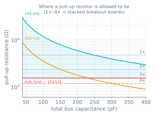
Now the part that catches people. Nearly every hobby breakout board has its own pull-ups already fitted, usually 4.7 kΩ. Wire several to the same bus and those resistors are in parallel:
| Boards on the bus | Effective pull-up | Verdict |
|---|---|---|
| 1 | 4700 Ω | Fine |
| 2 | 2350 Ω | Fine |
| 3 | 1567 Ω | Marginal — 34 Ω above the floor |
| 4 | 1175 Ω | Below the floor |
So the failure has a specific shape: one sensor works, two work, three work on a good day, and the fourth board makes the whole bus stop. Nothing is broken. The devices simply cannot pull the line low enough to be read as a low any more.
The fix is to remove the pull-up resistors from all but one board — they are usually two small surface-mount resistors marked 472, and the board’s documentation says which. Desoldering them feels wrong the first time and is the correct answer.
Scan the bus before you debug anything else
Before touching a library, ask the bus what is on it. This sketch tries every address and reports which ones answer:
#include <Wire.h>

void setup() {
  Wire.begin();
  Serial.begin(115200);
  while (!Serial) {}

  Serial.println(F("Scanning I2C..."));
  uint8_t found = 0;
  for (uint8_t addr = 1; addr < 127; addr++) {
    Wire.beginTransmission(addr);
    if (Wire.endTransmission() == 0) {
      Serial.print(F("  device at 0x"));
      Serial.println(addr, HEX);
      found++;
    }
  }
  Serial.println(found ? F("done") : F("nothing answered — check wiring and pull-ups"));
}

void loop() {}
The result tells you which problem you have:
- Nothing answers → wiring, power, or missing pull-ups. Not the library.
- The device answers at an unexpected address → an address strap pin is set differently than you assumed.
- The device answers, but the library returns zeroes → the bus is fine and the problem is above it.
That last line is worth the whole sketch. It cleanly separates “the wire is wrong” from “the code is wrong”, which is otherwise most of the debugging time.
Addresses, and the 0xD0 confusion
An I²C address is 7 bits. Sixteen values are reserved, leaving 112 usable.
Here is the trap. On the wire, the address is sent as seven bits followed by a read/write bit, so it looks like an 8-bit value. Datasheets frequently quote that 8-bit form. Arduino’s Wire library wants the 7-bit form.
An MPU-6050 datasheet says its address is 0xD0 for writing and 0xD1 for reading. The Wire library wants 0x68:
0xD0 = 1101 0000
0x68 = 0110 1000        the same bits, shifted right by one
If a device does not answer at the address printed in its datasheet, try that value shifted right by one before you conclude the board is dead. It is the most common I²C mistake there is.
When two devices want the same address
Addresses are set by the manufacturer, so collisions are routine. Three fixes, in order of how much you should like them:
1. An address strap pin. The cheapest fix, when the part has one. An MPU-6050 sits at 0x68, or 0x69 with its AD0 pin pulled high — so two of them coexist with one wire. A PCA9685 has six solder jumpers giving 64 addresses, which is why you can chain up to 62 boards on one bus.
2. Hold the others in reset while you re-address one. Some parts have a fixed address but can be reprogrammed at runtime. A VL53L0X is always 0x29 out of the box, and this is the standard way to run several: hold every sensor’s XSHUT pin low, bring one up, tell it to move to a new address, and repeat. The new address lives in RAM, so the sequence runs again at every boot.
3. A multiplexer. A TCA9548A is one device at 0x70 with eight switched buses behind it. Select a channel, talk to the device on it, select the next. It is the answer for eight identical sensors with no strap pin and no re-addressing — at the cost of a part, and of the bus being one-at-a-time.
Speed, length, and what actually breaks
I²C was designed to run between chips on one board. A robot stretches it across a chassis, which is where the limits start to bite.
- Capacitance is the real limit, not length. The specification allows 400 pF total. Ribbon cable adds roughly 50–100 pF per metre, and every device adds around 10 pF. Long runs fail by making the rising edge too slow — which the figure above shows as the ceiling falling.
- Slow down before you give up.
Wire.setClock(50000)halves the standard rate and buys real margin on a marginal bus. A robot polling a sensor at 100 Hz does not need 400 kHz. - Keep SDA and SCL apart. Running them as an adjacent pair in a ribbon couples clock edges into data. A ground wire between them helps.
- Clock stretching. A device that needs time may hold SCL low, and the controller must wait. Real hardware I²C handles it; some bit-banged implementations do not, and the symptom is a device that works alone and corrupts data when the bus is busy.
- A stuck bus. If a device was reset mid-transfer it can sit holding SDA low forever, and every scan returns nothing. Pulsing SCL nine times lets it finish the byte it thought it was sending and release the line — which is what the recovery routine in a good library is doing.
Mixing 3.3 V and 5 V
An ESP32 and a Raspberry Pi run their I²C at 3.3 V; an Uno runs it at 5 V. Because the bus is open-drain, the pull-up voltage decides the high level for everyone on it. Pull up to 5 V with a 3.3 V-only part attached and you are putting 5 V into a pin rated for 3.6 V.
Two things save you most of the time, and it is worth knowing which one you are relying on:
- Many “5 V compatible” breakouts are a 3.3 V chip with a regulator and level shifting already on the board. Check before assuming — the presence of a voltage regulator alone does not mean the signal pins are protected.
- Where they are not, a bidirectional MOSFET level shifter is the standard answer. A resistor divider is not: it breaks the open-drain behaviour in the direction that matters.
When it goes wrong
| Symptom | Usually |
|---|---|
| Scanner finds nothing at all | Missing pull-ups, swapped SDA/SCL, or no shared ground |
| Worked with three boards, dies with four | Parallel pull-ups below the sink-current floor |
| Device absent at its datasheet address | 8-bit address quoted; shift right by one |
| Two identical sensors, only one answers | Address collision — strap pin, XSHUT, or a multiplexer |
| Reads fine short, fails on a long cable | Bus capacitance; slow the clock or shorten the run |
| Intermittent corruption while motors run | Supply noise — see power and brown-outs |
| Scanner suddenly returns nothing after a crash | A device stuck holding SDA low; clock SCL nine times |
| Works alone, corrupts when the bus is busy | Clock stretching the controller is not honouring |
The useful habit is to run the scanner first, every time, before opening a library’s source. It takes thirty seconds and it splits the problem in half — and half of all I²C debugging is not knowing which side of the wire the fault is on.
Explore the graph
Part of these builds
Projects and learning paths that include this tutorial.
Further reading