
Component · Driver
PCA9685 Servo Driver
The PCA9685 drives 16 servos or PWM outputs over I²C from two pins—the standard way to run a robot arm or many servos without hogging the microcontroller.
What it is
The PCA9685 is a servo multiplier. A microcontroller has only a handful of hardware PWM channels, so driving a robot arm’s six servos—let alone a hexapod’s eighteen—quickly runs it out of pins and timers. This little board takes that job over: it generates 16 independent PWM signals in hardware, and you command all of them over two I²C wires. It’s the board behind most multi-servo robots.
How it works
You talk to the PCA9685 over I²C—the same two pins (SCL/SDA) can also carry other sensors. You set one PWM frequency for the whole chip (50 Hz for hobby servos), then set each channel’s pulse width to position its servo. Because the chip holds all 16 signals in hardware, the microcontroller just sends “channel 3 → 1.5 ms” and moves on; it never has to bit-bang the timing itself. That’s what keeps every servo smooth even when all 16 are moving. The pulse-width-to-angle idea is the same one covered on the SG90 servo page.
When to use it
Reach for a PCA9685 whenever a robot has more servos than the microcontroller has PWM pins, or when you want the servos rock-steady:
- Robot arms — several joint servos moving together (pair it with inverse kinematics).
- Hexapods / quadrupeds — a dozen or more legs’ worth of servos.
- Pan-tilt and camera rigs — freeing the microcontroller’s timers for other work.
For a single scanning servo—like the ultrasonic scanner on an obstacle-avoider—you don’t need it; the microcontroller can drive one servo directly.
Wiring and gotchas
- Two power rails. Logic (VCC) from the microcontroller; servo power from the V+ terminal. Never run 16 servos’ current through the Arduino’s 5 V.
- Size V+ for stall, not idle. Sixteen servos can pull several amps together; an undersized supply sags and the whole board jitters.
- Set unique addresses when chaining boards, via the solder jumpers.
- Add a capacitor across V+ to absorb the current spikes as servos start moving.
Pinout
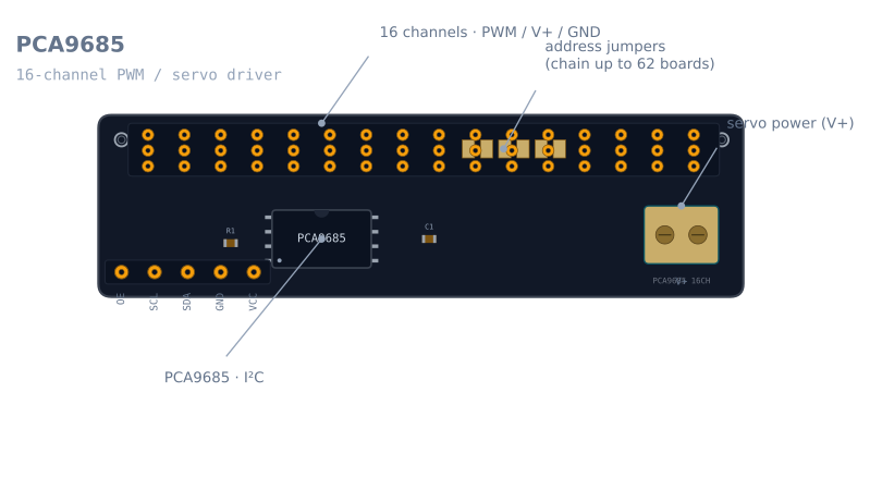
Three groups of connections: a control header you wire to the microcontroller, sixteen servo headers, and a power terminal that must not be confused with the first one.
| Group | Pin | What it does |
|---|---|---|
| Control | VCC | Logic power only, 3.3 V or 5 V from the microcontroller. Not the servos’ supply |
| Control | GND | Ground — must be common with both the microcontroller and the servo supply |
| Control | SCL | I²C clock |
| Control | SDA | I²C data |
| Control | OE | Output enable, active low. Left floating it is pulled low, so outputs are on |
| Power | V+ (screw terminal) | Servo current. Up to 6 V on the common breakout |
| Outputs | 0–15 | Three pins each: PWM signal, V+, GND — standard servo order |
| Address | A0–A5 (solder pads) | Six jumpers select the I²C address, 0x40 by default |
The single most consequential fact on this board is that VCC and V+ are different rails. VCC runs the chip; V+ runs the servos. Bridging them puts servo stall current through the microcontroller’s regulator, which is the fastest way to brown out an Arduino.
Wiring it to an Arduino
| PCA9685 | Arduino Uno | ESP32 | Note |
|---|---|---|---|
| VCC | 5 V | 3.3 V | A few milliamps — logic only |
| GND | GND | GND | Also common with the servo supply’s ground |
| SDA | A4 | GPIO 21 | The board has 10 kΩ pull-ups fitted |
| SCL | A5 | GPIO 22 | Same |
| V+ | not the Arduino | not the ESP32 | A separate 5–6 V supply sized for stall current |
| OE | Leave open | Leave open | Or drive it from a pin to kill all outputs at once |
OE is more useful than it looks. Pulling it high disables all sixteen outputs in hardware,
instantly, without an I²C transaction. On an arm that can drop under gravity that is a real
emergency stop, and it works even if your code has hung.
Sizing the servo supply
This is where most PCA9685 projects go wrong, and the arithmetic is not hard.
A hobby servo draws roughly:
| Servo | Idle | Moving, no load | Stalled |
|---|---|---|---|
| SG90 (9 g) | ~10 mA | ~150–250 mA | ~650 mA |
| MG90S (metal gear) | ~10 mA | ~250–400 mA | ~800 mA |
| MG996R (standard) | ~10 mA | ~500–900 mA | ~2.5 A |
Four SG90s on a small arm, all moving at once, is comfortably 1 A and can peak near 2.6 A if they all stall together — which is exactly what happens when the arm hits its own frame. A 1 A phone charger will not do it. Size for all your servos stalling simultaneously, or at minimum for all of them moving plus one stalled.
The symptom of an undersized supply is distinctive and confusing: the servos jitter, the board may reset, and it looks like an I²C or code problem. It is not. Put a meter on V+ while the arm moves and watch it sag.
Add a capacitor across V+. Something in the 470–1000 µF range, close to the terminal. It cannot carry a sustained stall — a 1000 µF cap supplying 1 A drops a volt every millisecond — but it does absorb the sharp current spike at the instant a servo starts, which is what couples into the logic rail.
How the PWM is actually generated
Understanding two numbers here makes every servo-driver problem easier to diagnose.
The chip runs from an internal 25 MHz oscillator and divides it down with a prescaler:
prescale = round(25000000 / (4096 x frequency)) - 1For the 50 Hz hobby servos want, that is round(25000000 / 204800) - 1 = 121.
Each period is then divided into 4096 steps (12-bit). At 50 Hz the period is 20 ms, so
one step is 20 ms / 4096 = 4.88 µs. That converts the servo pulse widths you actually care
about into the counts you write:
| Pulse width | What it means | Counts at 50 Hz |
|---|---|---|
| 1.0 ms | One end of travel | 205 |
| 1.5 ms | Centre | 307 |
| 2.0 ms | The other end | 410 |
Two consequences fall straight out of this. First, you get about 205 counts across a servo’s
full 180°, which is just under one count per degree — the PCA9685’s 12-bit resolution is
not the limiting factor on a hobby servo, the servo’s own deadband is. Second, the prescaler
can only be written while the chip is in sleep mode, which is why every library toggles
MODE1 around a frequency change.
The oscillator is not exactly 25 MHz
Real boards run a few percent off nominal, and it is consistent per board. If your servos are systematically short of their commanded angle at both ends, the fix is not to fudge the pulse widths — it is to measure and correct the clock:
pwm.begin();
pwm.setOscillatorFrequency(26075000);  // measured, not the 25 MHz nominal
pwm.setPWMFreq(50);
Measure it by commanding 50 Hz, putting a scope or a logic analyser on any output, and reading the true period. Scale the nominal 25 MHz by the ratio of commanded to measured frequency. Do this once per board and write the number in a comment.
Minimal working code
#include <Wire.h>
#include <Adafruit_PWMServoDriver.h>

Adafruit_PWMServoDriver pwm = Adafruit_PWMServoDriver(0x40);

// Per-servo calibration. These are NOT universal — measure your own.
const int SERVO_MIN = 150;   // counts at one end stop
const int SERVO_MAX = 600;   // counts at the other

int countsFor(int degrees) {
  return map(constrain(degrees, 0, 180), 0, 180, SERVO_MIN, SERVO_MAX);
}

void setup() {
  pwm.begin();
  pwm.setOscillatorFrequency(25000000);  // replace with your measured value
  pwm.setPWMFreq(50);                    // hobby servos want 50 Hz
  delay(10);
}

void loop() {
  for (int a = 0; a <= 180; a += 5) {    // sweep, don't jump
    pwm.setPWM(0, 0, countsFor(a));
    delay(20);
  }
  for (int a = 180; a >= 0; a -= 5) {
    pwm.setPWM(0, 0, countsFor(a));
    delay(20);
  }
}
The SERVO_MIN/SERVO_MAX constants are the calibration, and they differ per servo — even
between two of the same model from the same bag. Find them by stepping slowly outward from
307 and stopping the moment the servo buzzes without moving, which means it is pushing
against its own end stop and drawing stall current for nothing.
Note also the sweep rather than a jump. setPWM changes the commanded position instantly,
and the servo will attempt it at full speed — which on an arm means a violent movement and a
current spike. Stepping the command is the poor man’s motion profile, and it is worth doing
even in test code.
Chaining boards
Each board has six solder pads, A0 to A5, giving 64 addresses from 0x40. Bridge a
different combination on each board:
| Jumpers bridged | Address |
|---|---|
| none | 0x40 |
| A0 | 0x41 |
| A1 | 0x42 |
| A0 + A1 | 0x43 |
| A5 | 0x60 |
62 boards is the documented maximum — 0x70 is reserved for the I²C general-call address,
which is why it is not the full 64. In practice the limit arrives far sooner: 62 boards is
992 servos, and the power supply for that is a much larger engineering problem than the bus.
One thing to watch when chaining: every board carries its own 10 kΩ I²C pull-ups, and they parallel. Ten boards gives 1 kΩ, which is getting heavy for a 5 V bus. Past a handful of boards, cut the pull-up jumpers on all but one.
Troubleshooting
| Symptom | Likely cause | Fix |
|---|---|---|
| Nothing moves at all | No servo supply on V+ | V+ is a separate rail; VCC only powers the chip |
| Servos jitter constantly | Supply sagging under load | Size V+ for stall current; add a 470–1000 µF capacitor |
| Servos jitter only when several move | Same, but marginal | As above — measure V+ with a meter while moving |
| One servo buzzes and gets hot | Commanded past its end stop | Narrow that channel’s SERVO_MIN/SERVO_MAX |
| All angles consistently short | Oscillator is not exactly 25 MHz | Measure the real output frequency and call setOscillatorFrequency |
| Board not found on the bus | Wrong address, or no logic power | Scan the bus; check VCC and that the address jumpers match your code |
| Two boards, only one responds | Both on the default 0x40 |
Bridge address jumpers so each board is unique |
| Arduino resets when the arm moves | Servo current flowing through the board | V+ must come from its own supply, sharing only ground |
| Outputs dead but I²C works | OE held high |
Leave OE floating, or drive it low |
PCA9685 or direct microcontroller PWM?
| Direct PWM pins | PCA9685 | |
|---|---|---|
| Channels | 6 on an Uno, and the Servo library steals a timer |
16 per board, 62 boards on one bus |
| Pins used | One per servo | Two, total, for all of them |
| Timing | Generated by the microcontroller — jitters when the loop is busy | Generated in hardware — steady regardless of your code |
| Power path | Whatever you wire, often badly | A dedicated V+ terminal that makes the right answer obvious |
| Extra cost | None | A few dollars, plus an I²C address |
The honest threshold: one or two servos, drive them directly. A scanning sensor head on
an obstacle-avoider does not need this board. Three or more, or any servo whose smoothness
matters, and the PCA9685 pays for itself immediately — not because of the pin count, but
because the microcontroller stops being responsible for timing. A servo driven by the Servo
library will twitch whenever your loop stalls; one driven by a PCA9685 will not.
Explore the graph
Used in these builds
Projects, learning paths, and simulators that include the PCA9685 Servo Driver.
Questions
PCA9685 Servo Driver FAQ
What is a PCA9685?
The PCA9685 is a 16-channel, 12-bit PWM driver you control over I²C. It's most often used as a servo driver—one small board runs up to 16 servos from just two microcontroller pins, which is why it's the standard choice for robot arms, hexapods, and pan-tilt rigs.
How many servos can a PCA9685 drive?
16 per board, and you can chain up to 62 boards on one I²C bus for 992 channels. The limit in practice is power, not channels—16 servos moving at once can pull several amps, which must come from the separate V+ terminal, not the microcontroller.
Does the PCA9685 need a separate power supply?
Yes, for the servos. The chip's logic runs on 3.3–5 V from the microcontroller, but the servos draw their current from the dedicated V+ terminal—wire that to a supply that can deliver the stall current of all your servos at once, or they'll brown out and jitter.
How do you connect a PCA9685 to an Arduino?
Wire it over I²C—SDA and SCL to the Arduino's I²C pins, plus VCC and GND for the chip's logic power. Then connect a separate supply to the V+ terminal for the servos, and plug each servo into a channel header. A library (such as Adafruit's) lets you set each channel's angle in code.
How do you chain PCA9685 boards?
Each board has six solder-jumper pads that set its I²C address. Bridge a different combination on each board so every one has a unique address, then wire them all to the same two I²C lines—up to 62 boards, 992 channels, on one bus.
Further reading