
Component · Actuator
NEMA 17 Stepper Motor
The 42 mm stepper behind every 3D printer and small CNC. What the numbers mean, how to find the coil pairs, and why holding torque tells you almost nothing.
What it is
A NEMA 17 is a hybrid stepper motor in a 42 mm square frame. It is the motor in essentially every desktop 3D printer, most small CNC routers, laser engravers, camera sliders and pen plotters — not because it is special, but because the frame size hit a sweet spot and the entire hobby ecosystem standardised on it.
What a stepper offers that a DC gearmotor does not is position without feedback. Tell it to advance 3200 microsteps and, if you have not overloaded it, it has advanced 3200 microsteps — no encoder, no PID loop, no tuning. That is a genuinely large simplification, and it is the reason a 3D printer can cost a hundred pounds and still place a nozzle within a tenth of a millimetre.
The catch is in “if you have not overloaded it”, and it is a sharp catch rather than a gradual one. A stepper asked for more torque than it has does not slow down — it slips and loses position permanently, silently, in jumps of four full steps.
How it works
Inside is a permanent-magnet rotor with 50 teeth, and two coils arranged so that energising them in different combinations points a magnetic field in different directions. The driver rotates that field; the rotor follows it.
The 1.8° figure comes straight out of the tooth count: 50 rotor teeth × 4 field positions per magnetic cycle = 200 stable positions per revolution, so 360 ÷ 200 = 1.8°. Every “1.8° motor” you will meet has this same 50-tooth geometry, which is why one full step is always 90 electrical degrees regardless of the motor’s size or brand.
The rotor is never exactly where the field is — it trails behind by the lag angle, and the torque it produces is proportional to the sine of that angle. That single relationship is the whole of stepper behaviour, and it is worth reading once properly because it explains lost steps, microstepping, resonance and motor sizing all at the same time.
Reading the numbers
| Spec | What it actually tells you |
|---|---|
| Step angle 1.8° | 200 full steps/rev. Also that one full step = 90 electrical degrees. |
| Rated current 1.7 A | What to set on the driver — use 70–85% of it |
| Holding torque 0.44 N·m | Torque at zero speed only. Falls steeply once moving. |
| Resistance 2.8 Ω | With the current rating, the heat: 1.7² × 2.8 = 8 W per phase |
| Inductance 3.2 mH | How fast the driver can reverse current — this sets the top speed |
| Rotor inertia 54 g·cm² | What you have to accelerate before the load even counts |
| Body length 40 mm | The real torque indicator, and the only one the frame size hides |
The two most misread rows are holding torque and inductance.
Holding torque is a stationary measurement. It is real, it is what stops the axis being pushed out of position at rest, and it is almost irrelevant to a moving machine. Available torque falls as speed rises because the winding fights back — and inductance is how hard it fights. A low-inductance motor of the same torque rating will reach a much higher speed on the same supply, which is why serious machine builders read the inductance and casual ones read the torque.
The practical consequence is one line: more amps buy torque, more volts buy speed. If a machine stalls under load at slow speed, raise the current limit. If it stalls only when you speed it up, raise the supply voltage — turning the current up will not help, because past the corner speed the driver was never reaching the set current anyway.
Current, heat and the power budget
A stepper draws its full set current whenever it is energised, whether or not it is moving. This surprises people coming from DC motors, where a stalled-but-unloaded motor draws almost nothing.
Per motor, at a 1.2 A limit on a 2.8 Ω winding, both phases energised:
P = 2 × I² × R = 2 × 1.2² × 2.8 ≈ 8.1 WEight watts, continuously, per motor, at standstill. A three-axis machine with three NEMA 17s is dissipating around 24 W before it does anything. That drives three decisions:
- Supply sizing. The motor supply must carry every axis at once. Note that this is not
current limit × motorson the supply side — the chopper is a buck converter, so at 24 V the supply current is well under the phase current. Budget on power, not amps, and leave headroom; see the robot power budget. - Heat. 60–80 °C on the case is normal. Mount the motor to something metal where you can.
- Disabling. Pulling ENABLE high de-energises the coils and stops the heat, but the axis is then free to be pushed. Fine for X and Y on a plotter between jobs; dangerous for a Z axis that is holding weight up, unless the screw is self-locking.
Wiring it to a driver
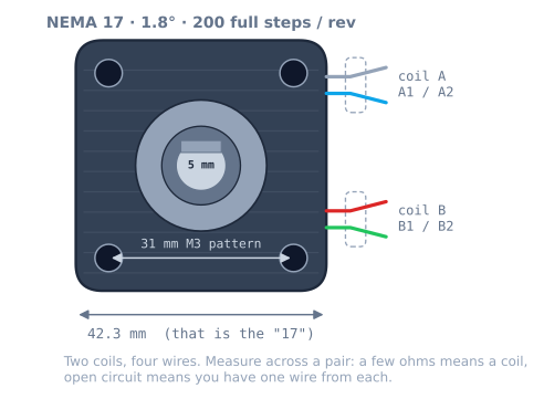
Four wires, two coils. Find the pairs with a multimeter on ohms — a pair reads a few ohms, a mismatch reads open circuit — then:
| Motor | A4988 pin |
|---|---|
| Coil A, wire 1 | 1A |
| Coil A, wire 2 | 1B |
| Coil B, wire 1 | 2A |
| Coil B, wire 2 | 2B |
Order within a pair only reverses the direction, so if the axis runs backwards you can swap two wires instead of editing firmware. Order between pairs is the one that matters: get it wrong and the motor buzzes and vibrates without turning, because the field is no longer rotating in a coherent sequence.
Never disconnect a motor while the driver is powered. An energised coil interrupted mid-chop produces a voltage spike with nowhere to go, and that spike is what kills drivers.
Some motors ship with six or eight wires — those are unipolar or dual-bipolar windings. For a bipolar driver like the A4988, use the four wires that form the two full coils and tape off the centre taps; you get more torque that way than wiring them as unipolar.
Minimal working code
Pulses on one pin, direction on another. There is no library in this and none is needed:
const int STEP_PIN = 3, DIR_PIN = 4, EN_PIN = 5;
const float STEPS_PER_MM = 80.0;     // 20T GT2 pulley at 1/16 stepping

void setup() {
  pinMode(STEP_PIN, OUTPUT);
  pinMode(DIR_PIN, OUTPUT);
  pinMode(EN_PIN, OUTPUT);
  digitalWrite(EN_PIN, LOW);          // active low: energise
}

// Blocking, unramped. Fine for a bench test, wrong for a machine.
void moveMillimetres(float mm, unsigned stepDelayUs) {
  digitalWrite(DIR_PIN, mm >= 0 ? HIGH : LOW);
  long steps = lround(fabs(mm) * STEPS_PER_MM);
  for (long i = 0; i < steps; i++) {
    digitalWrite(STEP_PIN, HIGH);
    delayMicroseconds(2);
    digitalWrite(STEP_PIN, LOW);
    delayMicroseconds(stepDelayUs);
  }
}

void loop() {
  moveMillimetres(50, 300);
  delay(500);
  moveMillimetres(-50, 300);
  delay(500);
}
That will run a motor on the bench. It is also the version to move away from immediately, because the step rate jumps from zero to full instantly — above the motor’s pull-in rate that produces a loud buzz and no motion at all. For anything real, add an acceleration profile or hand it to AccelStepper, and use the non-blocking timing pattern so the endstops still get read.
Sizing one: a worked example
Pick the motor from the load, not from a forum post. The arithmetic is short.
The machine: a belt-driven X axis, 20-tooth GT2 pulley (40 mm per revolution), a 300 g carriage, running up to 200 mm/s with 2000 mm/s² of acceleration.
Step 1 — what torque does the motion need? Convert the linear world to the shaft. The pulley’s
effective radius is 40 mm ÷ 2π = 6.37 mm:
accelerating the carriage:  F = m·a = 0.3 kg × 2.0 m/s² = 0.6 N
                            T = F × r = 0.6 × 0.00637 = 0.004 N·m
friction (rails, belt, a dragging cable) ≈ 5 N
                            T = 5 × 0.00637 = 0.032 N·m
rotor's own inertia:        α = a ÷ r = 2.0 ÷ 0.00637 = 314 rad/s²
                            T = J·α = 5.4e-6 × 314 = 0.002 N·m
                                                     ─────────────
                                              total ≈ 0.038 N·m
The result is worth sitting with: friction is eight times the accelerating torque. On a light machine the load is almost entirely friction, which means a binding rail costs you far more margin than a heavier carriage would. Measure the friction before buying a bigger motor.
Step 2 — what speed does it need? 200 mm/s ÷ 40 mm/rev × 60 = 300 rpm.
Step 3 — read the torque curve at that speed, not the headline. A 0.44 N·m motor at a 1.2 A limit on 24 V is still flat at 300 rpm, so about 0.31 N·m is available.
Step 4 — check the margin. 0.038 ÷ 0.31 = 12%. In lag-angle terms, sin⁻¹(0.12) = 7° of the
90° available. That is a very comfortable margin, and it should be — the number you compute is
always optimistic, because it does not include the bearing that stiffens in winter, the cable chain
that snags, or the belt you tensioned harder than you meant to.
| Margin used | Lag angle | Verdict |
|---|---|---|
| Under 25% | Under 15°e | Comfortable — this is where to design |
| 25–50% | 15–30°e | Fine, but measure before you go faster |
| 50–70% | 30–45°e | Tight. One cold morning away from skipping. |
| Over 70% | Over 45°e | Expect intermittent, unexplainable step loss |
| 100% | 90°e | It is already failing |
The usual “size it at half the available torque” advice lands in the second row, which is the right place to be. Anything past the fourth row produces the most frustrating class of fault there is: a machine that works on the bench, works in a demo, and fails once an hour in real use.
The same axis on a lead screw tells you why the mechanism matters. A T8’s effective radius for
this purpose is 8 mm ÷ 2π = 1.27 mm, five times smaller — so the same 5 N of friction is only
0.0064 N·m at the shaft, a 2% margin. The trade is speed: the screw needs five times the step rate
for the same travel, which is the ceiling in steps per millimetre.
Six and eight-wire motors
Most NEMA 17s sold today have four wires and are unambiguously bipolar. Older and industrial stock often has six or eight, and the extra wires are taps on the windings:
| Wires | What you have | How to drive it from an A4988 |
|---|---|---|
| 4 | Two plain coils | Connect them. Nothing to decide. |
| 6 | Two coils with a centre tap each | Ignore the centre taps, tape them off, use the ends |
| 8 | Four half-coils | Wire each pair in series for torque, parallel for speed |
The six-wire case is the one to get right. Using the centre tap and one end — driving it as a unipolar motor — energises half of each winding and costs you roughly 30% of the torque, for no benefit at all with a bipolar driver. Find the two ends of each winding (the pair with the highest resistance between them; the centre tap reads about half that to either end), use those, and insulate the taps.
For eight-wire motors, series wiring doubles both the inductance and the resistance, which raises torque at low speed and lowers the corner speed. Parallel does the opposite. Series is the right default for a machine that carries load; parallel is for one that has to move quickly.
Troubleshooting
| Symptom | Cause | Fix |
|---|---|---|
| Vibrates loudly, does not turn | Coil pairs wired across each other | Re-pair with a meter on ohms |
| Buzzes at the start of every move | Commanded rate above the pull-in rate | Add an acceleration ramp |
| Loses position by a few mm per job | Losing steps on ramps | Lower acceleration, raise current, or slow down |
| Fine slow, stalls fast | Past the corner speed | Raise the supply voltage, not the current |
| Weak at all speeds | Current limit too low | Re-measure Vref against the sense resistor |
| Too hot to touch for a second | Current limit above rating | Check the arithmetic; add airflow |
| Rough and noisy at one speed only | Mid-band resonance | Change microstepping, or avoid that speed |
| Holds fine but drifts when powered off | Coils de-energised, axis backdriven | Use a self-locking screw, or keep it enabled |
| Turns the wrong way | Coil polarity | Swap the two wires of one pair |
NEMA 17, or the alternatives?
| Option | Torque | Position feedback | Pick it when |
|---|---|---|---|
| NEMA 17 stepper | 0.25–0.65 N·m | None — open loop | Precise, repeatable linear motion |
| NEMA 23 stepper | 1.0–3.0 N·m | None | A 17 stalls at the speed you need |
| N20 encoder motor | Low, geared | Encoder — closed loop | Wheels; you want speed control, not position |
| DC gearmotor | Varies | None | Driving wheels where exact position is irrelevant |
| SG90 servo | 0.15 N·m | Internal pot, closed loop | A joint over a limited angle, cheaply |
| Closed-loop stepper | As NEMA 17 | Encoder on the back | You cannot tolerate a silent lost step |
The honest summary is that a stepper is the right answer when you need repeatable position along an axis and can guarantee the torque margin. It is the wrong answer for a drive wheel: wheels slip, slipping is unbounded, and a motor that loses position silently is the last thing you want under a robot that is trying to do odometry.
Where it is used
This motor is the actuator behind the pen plotter build, and it is the part the whole precision motion roadmap is about. You can see how it behaves — lag angle, step loss, microstepping — without buying one, in the stepper simulator.
Explore the graph
Used in these builds
Projects, learning paths, and simulators that include the NEMA 17 Stepper Motor.
Compare
Alternatives
Questions
NEMA 17 Stepper Motor FAQ
What does NEMA 17 actually mean?
It is a mounting standard, not a performance rating. NEMA 17 specifies a 1.7 inch square faceplate — 42.3 mm — with four M3 holes on a 31 mm pattern and a 22 mm pilot boss. Nothing else. Two NEMA 17 motors can differ by a factor of three in torque, because the standard says nothing about the body length, and body length is where the torque lives. A 20 mm "pancake" and a 60 mm motor are both NEMA 17.
How do I find which wires are a pair?
With a multimeter on resistance. Two wires from the same coil read a few ohms between them; two wires from different coils read open circuit. Pair them by continuity, connect one pair to the driver's 1A and 1B, the other to 2A and 2B. Within a pair the order only reverses the direction, so if the motor turns the wrong way you can swap those two wires instead of changing the firmware. If the motor vibrates loudly and does not rotate, the pairing is wrong.
Why does my motor get so hot?
Because a stepper draws its full set current whenever it is energised, including when it is holding still doing nothing. That is how it holds position, and it means a stepper at rest dissipates about as much as one that is working. A case temperature of 60 to 80 °C is normal and is not a fault. If it is too hot to touch for a second, check that the driver's current limit actually matches the motor's rating, and consider disabling the motor when the axis does not need to hold.
Is holding torque the torque I can use?
No, and this catches nearly everyone. Holding torque is measured with the shaft stationary at rated current. As soon as the motor turns, winding reactance and back-EMF cut the current the driver can push in, so the available torque falls — on a typical 24 V setup it is flat to roughly 600 rpm and heading toward zero by 1200. Size against the torque curve at your actual working speed, and leave margin: a load at 100 percent of available torque sits exactly at the pull-out point with nothing to spare.
Should I use a NEMA 17 or a NEMA 23?
NEMA 17 until the torque genuinely runs out. A NEMA 23 is a 57 mm frame with two to four times the torque, but it is heavier, needs a bigger driver and a bigger supply, and its extra rotor inertia makes it harder to accelerate. For a pen plotter, a small gantry, a camera slider or a 3D printer, a NEMA 17 is the right answer. Move up when a NEMA 17 at a sensible current limit stalls at the speed you need.
Can I drive a stepper without a driver board?
Not usefully. A stepper coil is a low-resistance inductor — connect 24 V across 2.8 Ω and Ohm's law gives 8.6 A, which destroys the motor. The driver's job is to regulate current by chopping, and that is not something you can do with an H-bridge and a delay loop at any useful speed. An L298N can technically drive one, but it is a voltage-mode bridge with no current control, so you get a fraction of the torque and a lot of heat.
Further reading