
Tutorial · Beginner · 25 min
Steps Per Millimetre: Belts, Lead Screws, Resolution
Where 80 and 400 steps/mm come from, why a belt and a screw trade resolution for speed, and how to calibrate the number against a ruler instead of trusting it.
One number, one formula
A stepper driver counts pulses. Your machine moves in millimetres. The number that converts between them is steps per millimetre, and every other calibration on the machine depends on it being right.
The formula never changes:
steps/mm = (full steps per revolution × microstepping) ÷ travel per revolutionThe numerator is fixed by the motor and the driver — a 1.8° motor at 1/16 stepping gives 200 × 16 = 3200 microsteps per revolution, always. The denominator is the only part that depends on your machine, and it is a question about mechanics: how far does the axis move when the shaft turns once?
Belts
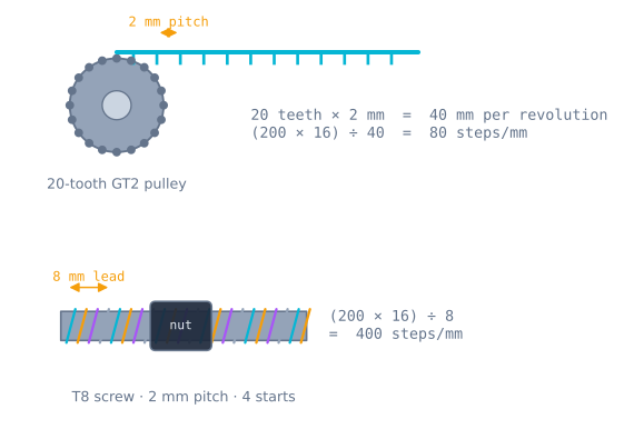
For a toothed belt, travel per revolution is just the teeth on the pulley times the belt’s pitch. GT2 belt has a 2 mm pitch, and a 20-tooth pulley is the default on almost every hobby machine:
travel  = 20 teeth × 2 mm = 40 mm per revolution
steps/mm = (200 × 16) ÷ 40 = 80
There it is — the 80 steps/mm in every 3D printer’s X and Y configuration. It is not a magic constant; it is 20-tooth GT2 at sixteenth stepping, and if you fit a 16-tooth pulley it becomes 100.
| Pulley | Travel per rev | steps/mm at 1/16 | Resolution |
|---|---|---|---|
| 16-tooth GT2 | 32 mm | 100 | 0.010 mm |
| 20-tooth GT2 | 40 mm | 80 | 0.0125 mm |
| 30-tooth GT2 | 60 mm | 53.33 | 0.019 mm |
| 20-tooth GT3 (3 mm) | 60 mm | 53.33 | 0.019 mm |
Note the 30-tooth row does not divide evenly. 53.333… steps/mm is perfectly legal — firmware stores it as a float and accumulates fractional steps — but it does mean no position is ever exactly on a step boundary, which is one small argument for the tooth counts everyone else uses.
Lead screws
For a screw, travel per revolution is the lead — and lead is not pitch. This is the most common mistake in the whole topic.
- Pitch is the distance between adjacent threads.
- Lead is how far the nut travels in one turn.
- Lead = pitch × number of starts.
A single-start screw has lead equal to pitch. But the ubiquitous “T8” screw is 2 mm pitch with four separate thread helices wound alongside each other, so one turn advances the nut by four threads:
lead     = 2 mm pitch × 4 starts = 8 mm per revolution
steps/mm = (200 × 16) ÷ 8 = 400
And there is the other number you have seen. If you measure the thread spacing on a T8 with calipers you get 2 mm, calculate 1600 steps/mm, and every move comes out four times too short. Count the thread starts at the end of the screw — you can see the four separate helices — or just turn it one full revolution against a ruler.
| Screw | Pitch | Starts | Lead | steps/mm at 1/16 |
|---|---|---|---|---|
| T8, 4-start (“T8x8”) | 2 mm | 4 | 8 mm | 400 |
| T8, 2-start (“T8x4”) | 2 mm | 2 | 4 mm | 800 |
| T8, single start (“T8x2”) | 2 mm | 1 | 2 mm | 1600 |
| M5 threaded rod | 0.8 mm | 1 | 0.8 mm | 4000 |
| Ball screw 1605 | 5 mm | 1 | 5 mm | 640 |
Choosing between them
Resolution is not free. A screw with ten times the resolution of a belt also needs ten times as many pulses for the same distance — so at a fixed maximum step rate it is ten times slower. That is the trade, and it is a hard one:
| GT2 belt, 20T | T8 lead screw | |
|---|---|---|
| Travel per revolution | 40 mm | 8 mm |
| Resolution at 1/16 | 0.0125 mm | 0.0025 mm |
| Steps/s for 100 mm/s | 8 000 | 40 000 |
| Practical top speed | 300+ mm/s | ~30 mm/s |
| Force at the axis | Low — belt stretches | High — 5× mechanical advantage |
| Holds position unpowered | No | Usually yes (self-locking) |
| Backlash | Low if tensioned | Real, and in the nut |
| Use it for | X and Y — fast, light | Z — slow, heavy, must not drop |
This is exactly why a 3D printer uses belts for X and Y and a screw for Z. X and Y move fast and carry almost nothing. Z moves slowly, carries the weight of a bed or a gantry, and must not sag when the power goes off — and a T8’s shallow helix angle makes it self-locking, so it will not backdrive under load.
The 40 000 steps/s figure in that table is also a real ceiling, not a theoretical one. An Arduino Uno bit-banging step pulses tops out around 10 000 to 15 000 per second before the loop cannot keep up, which on a T8 at 1/16 stepping is about 30 mm/s. If you need a screw axis to move faster than that, the answers are fewer microsteps, a faster board, or a hardware timer — not a bigger motor.
Torque, and the thing the table does not say
Changing the mechanism changes the load the motor sees, not just the speed. A lead screw multiplies force by roughly 2π × radius ÷ lead, so a T8 turns a modest motor torque into a substantial axial force — which is why a Z axis with a small motor can lift a heavy bed.
The belt does the opposite. A 20-tooth GT2 pulley has a 12.7 mm pitch diameter, so belt tension is motor torque divided by 6.4 mm. A motor making 0.3 N·m produces about 47 N at the belt, and that is all you get. If your X axis skips steps when it hits something, this arithmetic is why.
The reflected inertia changes too, and in the same direction: the finer the mechanism, the less the carriage’s mass matters to the motor, which is part of why a screw axis tolerates aggressive acceleration that a belt axis does not. You can see the effect directly in the stepper simulator — switch the mechanism from belt to lead screw with everything else held constant and watch what happens to the lag angle.
Calibrate it, do not trust it
The calculated number is a starting point, not an answer. Belts stretch, pulleys have manufacturing tolerance, and screws are sold with optimistic descriptions. Measure:
- Mark the carriage against a fixed reference. A strip of tape and a sharp pencil line.
- Command a long move — 100 mm, not 10 mm. Error is a percentage, so a longer move measures it more precisely.
- Measure what actually happened with calipers or a steel rule.
- Correct with a ratio:
new steps/mm = old steps/mm × (commanded ÷ measured)Commanded 100 mm, measured 98.4 mm, currently on 80: 80 × 100 ÷ 98.4 = 81.3 steps/mm.
Then repeat the measurement to confirm. A single correction that does not converge means the error is not a scale error — and the difference is diagnostic:
| Measurement pattern | Cause |
|---|---|
| Off by a constant percentage at every distance | Wrong steps/mm — the calculation above fixes it |
| Off by a constant amount regardless of distance | Backlash or a loose pulley grub screw |
| Off by a different amount every time | Losing steps — current, speed, or acceleration |
| Correct one way, short the other way | Backlash, and you measured in both directions |
| Exactly 2×, 4× or 16× wrong | Microstepping jumpers do not match the firmware |
| Exactly 4× short on a screw axis | You used pitch where you needed lead |
That last two rows catch most first-time builds, and both are arithmetic rather than mechanics.
Rotary axes: steps per degree
Not every axis is linear. A rotary table, a filament extruder, a camera slider’s pan axis and a robot joint all have the same question with a different denominator — and for a rotary axis the denominator is usually a gear ratio rather than a mechanism:
steps/degree = (full steps × microstepping × gear ratio) ÷ 360A 1.8° motor at 1/16 through a 5:1 reduction gives (200 × 16 × 5) ÷ 360 = 44.4 steps per degree,
which is 0.0225° of resolution. Worth noticing: that is the same arithmetic as a belt, with 360
degrees standing in for the millimetres per revolution.
The extruder on a 3D printer is the odd one out, because it is quoted in steps per millimetre of filament while being a rotary drive. The denominator is the hobbed gear’s effective circumference, which is not its nominal diameter — the teeth bite into the filament, so the real grip radius is smaller than the one printed on the part. That is why nobody calculates E-steps and everybody measures them:
- Mark the filament 120 mm above the extruder inlet.
- Extrude exactly 100 mm.
- Measure from the inlet to the mark again. If it reads 27 mm, you extruded 93 mm, not 100.
new = old × 100 ÷ 93. With 93 steps/mm that is 100 steps/mm.
The 120 mm start point is deliberate: it leaves enough filament that the mark never reaches the inlet even if the extruder over-extrudes badly.
Non-integer steps per millimetre
Once you calibrate, the number stops being round — 80 becomes 81.3, and a 10 mm move becomes 813.0 steps. Firmware handles this correctly, but hand-rolled code usually does not, because the obvious implementation throws away the fraction on every move:
// Wrong: truncates on every call. Two hundred 0.1 mm moves land 1.4 mm short.
long stepsFor(float mm) { return (long)(mm * stepsPerMm); }
At 81.3 steps/mm, a 0.1 mm move is 8.13 steps, which truncates to 8. The 0.13 is discarded, and it is discarded again on the next move, and the next. Over a few hundred short segments — which is exactly what a curve or an infill pattern is — the error accumulates into something visible.
The fix is to keep the remainder rather than the position:
// Right: carry the fraction forward, so the error never accumulates past one step.
float carry = 0;

long stepsFor(float mm) {
  float exact = mm * stepsPerMm + carry;
  long whole = lround(exact);
  carry = exact - whole;        // always within half a step
  return whole;
}
Now the worst error at any moment is half a step — 0.006 mm on this axis — and it never grows. This is the same trick Bresenham line rasterisation uses, and the same reason firmware tracks position in steps rather than in millimetres: an integer step count cannot drift, and a float millimetre position can.
In firmware
Marlin and GRBL both keep the number as a settable parameter, so you rarely need to recompile:
; Marlin — X, Y, Z, E
M92 X80 Y80 Z400 E93
M500          ; save to EEPROM

; GRBL
$100=80       ; X steps/mm
$101=80       ; Y
$102=400      ; Z
Write down what you set. The most frustrating version of this problem is a machine that was calibrated correctly once, reflashed, and silently reverted to the firmware defaults.
Next
The number above tells the machine how far it has moved. It says nothing about where it started — and an open-loop machine has no way to know that on power-up. That is what homing against an endstop is for.
Explore the graph
Part of these builds
Projects and learning paths that include this tutorial.
Further reading