
Tutorial · Beginner · 30 min
Reading Analog Voltages: ADC References and Dividers
analogRead returns a ratio, not a voltage. Picking a reference that does not sag, sizing a divider, and building a battery monitor that tells the truth.
Introduction
analogRead() is the friendliest function on an Arduino and one of the most quietly misleading. It hands back a number between 0 and 1023, everybody treats that number as a voltage, and most of the time nothing goes wrong.
It goes wrong on a robot, because a robot has motors, and motors move the very thing that number is measured against.
analogRead returns a ratio
The ADC does not measure volts. It compares its input against a reference and reports the ratio:
reading = 1023 × V_in / V_refOn an Arduino Uno V_ref defaults to AVCC — the board’s 5 V rail. So analogRead() is really answering “what fraction of the 5 V rail is this?”, and converting it to volts by multiplying by 5/1023 is only correct while the rail is exactly 5 V.
You already know it is not, whenever the motors are running.
The reference is the bug
Wire a battery through a divider into A0 and watch the number while the motors start.
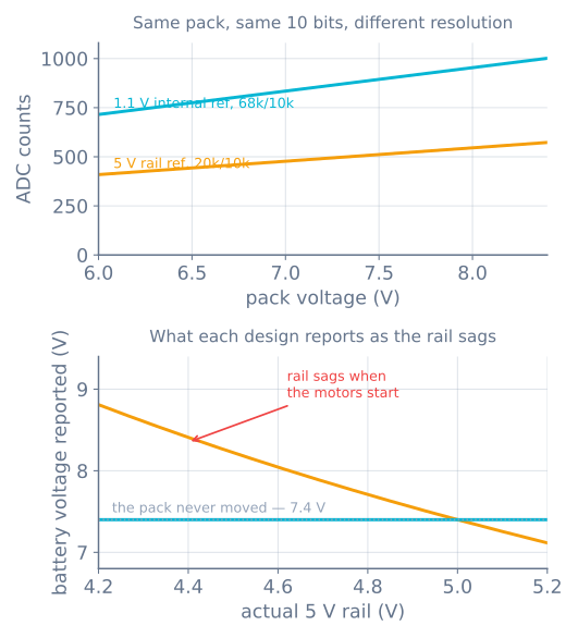
A low-battery cutoff built on the first design does the opposite of its job: the harder the robot works, the healthier the battery looks. And the failure is silent, because every individual reading is a perfectly valid ratio.
The fix is a reference that does not move. The ATmega328P has a 1.1 V bandgap reference on board:
analogReference(INTERNAL);   // 1.1 V on an Uno; INTERNAL1V1 on a Mega
analogRead(A0);              // discard — the reference needs a moment to settle
Always throw the first reading away after switching reference. The internal reference and the input capacitor both need time, and the first sample is taken before they have had it.
Sizing the divider
The reference is now 1.1 V and your pack is 8.4 V, so the divider has to bring the top of the range just under the reference:
V_adc = V_pack × R2 / (R1 + R2)With R1 = 68 kΩ and R2 = 10 kΩ the ratio is 0.128, so a full 8.4 V pack presents 1.077 V — just under the reference, using nearly the whole scale. Three numbers worth checking on any divider you design:
| Check | This divider | Why |
|---|---|---|
| Top of range vs reference | 1.077 V vs 1.1 V | Over the reference and it clips flat |
| Quiescent current | 108 µA | Drains 2.6 mAh a day — negligible against 2000 mAh |
| Output impedance (R1∥R2) | 8.7 kΩ | Keep under ~10 kΩ, see below |
Compare that with the naive version — a 20 kΩ/10 kΩ divider read against the 5 V rail. It puts a full pack at 2.80 V, which is 573 counts of a possible 1023, and it uses 164 counts across the pack’s whole 6.0–8.4 V range against the better design’s 286. Nearly twice the resolution, for the same two resistors and one line of code.
Resolution is not accuracy
Ten bits against a 5 V reference is 4.88 mV per step; against the 1.1 V reference it is 1.07 mV. Neither number is your accuracy.
What actually limits you:
- Reference tolerance. The bandgap is nominally 1.1 V and varies by a few percent between chips. That is a fixed scale error, so measure it once per board: feed in a known voltage, read the counts, and solve for the real reference. Store that constant. This is a calibration step, not an optional refinement.
- Noise. A robot’s supply is noisy, and averaging is the cheap answer. Averaging N samples reduces random noise by √N — 16 samples is 4× quieter, one extra bit of usable resolution. It does nothing for a scale error.
- Source impedance. The ADC charges a small sample-and-hold capacitor through whatever it is connected to. A high-impedance source cannot fill it in the time allowed, and the residue from the previously read channel is still in there.
That last one produces a distinctive bug worth naming.
Channels that read like their neighbours
Read A0 and A1 in turn with high-impedance sources and each reading is pulled toward the previous one. Sweep a potentiometer on A0 and watch A1 move in sympathy. Nothing is wired wrong.
Two fixes, and you can use both:
int readSettled(uint8_t pin) {
  analogRead(pin);        // charge the sample-and-hold on this channel
  return analogRead(pin); // then take the one you keep
}
Reading twice and discarding the first gives the capacitor a second sampling window to reach the new voltage. The other fix is to lower the source impedance — which is why the divider above uses 68 kΩ/10 kΩ rather than the 100 kΩ/100 kΩ that looks tidier and gives a 50 kΩ output impedance.
Where this shows up on a robot
- Battery monitoring, as above — and it is what makes a low-voltage cutoff trustworthy enough to protect a Li-ion pack.
- Analog line sensors. An IR reflectance array gives a continuous value per sensor, which is what lets a line follower compute a smooth position rather than a left/right flag. Those sensors are read against the same rail the motors are sagging, which is one reason a line follower’s calibration drifts as the battery empties.
- Current sensing, a shunt or Hall sensor whose output is a voltage.
- Potentiometers as tuning knobs, which is the friendliest way to tune a PID gain without reflashing.
- Not for a 3.3 V board’s 5 V sensor. An ESP32 or Raspberry Pi needs the divider for protection, not just for range.
When it goes wrong
| Symptom | Usually |
|---|---|
| Battery reading rises when the motors start | Referenced to the sagging rail; use INTERNAL |
| Reading pinned at 1023 | Input above the reference — divider ratio too high |
| One channel echoes the one read before it | Source impedance too high; read twice and discard |
| Readings jump around by tens of counts | Supply noise; average, and check the power rails |
| Voltage consistently off by a few percent | Uncalibrated internal reference — measure it once |
First reading after analogReference() is wrong |
Expected; discard it |
| Line sensor calibration drifts as the battery empties | Rail-referenced readings on a falling rail |
| Only 15% of the range used | Divider sized for 5 V while reading against 1.1 V |
The rule that prevents most of this: decide what your reference is before you decide anything else. Every number the ADC gives you is relative to it, so a reference that moves makes every reading a story about two things at once.
Explore the graph
Part of these builds
Projects and learning paths that include this tutorial.
Further reading