
Tutorial · Beginner · 18 min read
Ultrasonic vs Time-of-Flight Robot Sensors
Compare ultrasonic and time-of-flight distance sensors for a robot, then mount, calibrate, filter, and validate them for reliable obstacle avoidance.
A range sensor gives a robot something a bumper cannot: time to react before contact. It does not replace the bumper — a contact switch catches the black chair leg, the glass and the obstacle at the wrong height that every range sensor misses. Two common low-cost choices are ultrasonic sonar and optical time-of-flight (ToF). Both report distance, but they interact with surfaces differently. Choosing by maximum advertised range alone produces fragile obstacle avoidance.
The useful question is: which sensor gives valid measurements for the targets, lighting, geometry, update rate, and stopping distance of this robot?
Understand how each sensor measures
An ultrasonic sensor emits a burst of sound above human hearing and measures the echo time. Distance is approximately half the round-trip travel time multiplied by the speed of sound. The division by two accounts for the trip to the target and back.
An optical time-of-flight sensor emits modulated infrared light and estimates distance from the returning signal. Devices such as the VL53 family contain the timing and signal processing internally and usually expose results over I²C.
Their failure modes differ:
- Sound can reflect away from angled, soft, narrow, or acoustically absorbent targets.
- Multiple ultrasonic sensors can hear one another unless triggered in a controlled schedule.
- Optical sensors can struggle with low-reflectance targets, strong ambient infrared, cover-glass crosstalk, or targets outside their field of view.
- Neither type automatically knows whether a result is trustworthy; use status and signal-quality data when available.
Choose from the scene and control loop
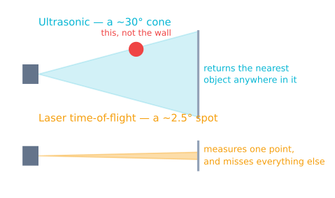
Ultrasonic modules are useful when cost matters, targets are reasonably broad, and a wider acoustic beam is acceptable. They can detect transparent objects that challenge some optical methods. Their beam can also report a nearby wall that is not directly in front of the robot.
ToF modules are compact, have controllable timing on many devices, and can provide a narrower region of interest. Multiple identical I²C sensors may require shutdown pins or an address-assignment sequence. Strong sunlight and dark surfaces must be tested on the actual platform.
Before buying hardware, write four requirements:
- Minimum and maximum useful distance.
- Required update period.
- Smallest obstacle that must be detected.
- Worst target and environment: black fabric, glass, angled wall, sunlight, or cross-traffic.
Then compare those requirements with the manufacturer data sheet, not a marketplace summary.
Mount for the measurement you need
Put the sensing axis where the robot needs clearance information, not merely where a bracket fits. A sensor high on the chassis may miss low obstacles; one too low may see floor reflections or wheel hardware. Keep the bumper and chassis outside the field of view.
For reactive steering, front-left, front-center, and front-right measurements are more informative than one forward beam. However, three sensors do not have to fire simultaneously. Schedule ultrasonic pings separately and leave enough time for echoes to decay.
Rigid mounting matters. Vibration changes the pointing direction and cable movement can corrupt marginal connections. If an optical sensor sits behind a protective window, follow the manufacturer’s crosstalk-calibration procedure for that exact mechanical stack.
Calibrate offset and test repeatability
Place a large flat target perpendicular to the sensor at several accurately measured distances across the working range. Capture at least 50 readings at each point. Record:
- mean or median reported distance;
- spread, such as minimum/maximum or standard deviation;
- invalid-status count;
- ambient conditions and target material.
A nearly constant difference is an offset and may be corrected after understanding its cause. Error that changes with distance needs a better model or a narrower trusted range. Do not fit a complex curve to a loose bracket or bad supply.
For a ToF module, run the specified offset calibration before crosstalk calibration. Store calibration data and load it on startup if the device API requires that. Recalibrate after changing the cover window or mounting geometry.
Filter invalid readings before smoothing
Treat a timeout, out-of-range code, or low-quality status as invalid—not as zero centimetres. Zero can command an emergency stop, so turning communication errors into zero creates unsafe behavior.
A median of the last three or five valid samples rejects isolated spikes without averaging them into the control signal:
if (measurement.valid) {
  window.push(measurement.distanceMm);
  if (window.size() > 5) window.popOldest();
  filteredDistance = median(window);
}
A low-pass filter gives a smoother display but adds lag. The sensor filtering tutorial explains that trade-off. Keep the raw value and validity status in logs so filtering does not hide a failing sensor.
Turn distance into a safe stopping rule
Obstacle avoidance must account for motion. A useful threshold includes braking distance, measurement delay, computation and actuator delay, and a margin:
stopThreshold = speed² / (2 × deceleration) + speed × delay + margin
Measure achievable deceleration on the real surface instead of assuming it — it is the traction limit µg, not anything the motors decide, and the worked arithmetic is here. At higher speed the braking term grows with speed squared, so a fixed 15 cm threshold is not equally safe at every command.
Use hysteresis to prevent chatter: enter the stopped state below one threshold and resume only above a larger threshold. Require a small number of consistent valid readings for normal steering, while retaining an intentionally conservative response to a credible close obstacle.
Validate difficult targets
Build a test matrix with a flat wall, angled wall, narrow pole, dark fabric, transparent panel, and moving obstacle. Test near the minimum range, near the intended stopping threshold, and near maximum operating range. Repeat under indoor lighting and sunlight if the robot will see both.
Measure detection rate and latency, not just average distance. A sensor that is accurate 90% of the time but periodically freezes for half a second may be unacceptable for a fast robot.
Diagnose the common failures
- Stable offset everywhere: verify the physical reference point, then apply manufacturer calibration.
- Random short ultrasonic readings: look for crosstalk, electrical noise, or late echoes from nearby structures.
- ToF readings worsen behind a window: perform offset and crosstalk calibration for that cover material.
- The robot oscillates near a wall: add hysteresis and reduce filter lag before retuning steering.
- It detects walls but misses chair legs: the beam geometry and mounting do not cover the required target.
- It stops too late only at high speed: threshold logic ignores braking distance and latency.
Use the Obstacle Avoidance Simulator to experiment with range, field of view, steering, and stopping distance before transferring the thresholds to hardware.
Explore the graph
Part of these builds
Projects and learning paths that include this tutorial.
Further reading