
Tutorial · Intermediate · 20 min read
ROS 2 TF2 Coordinate Frames for Mobile Robots
Understand the ROS 2 TF2 transform tree, map, odom, base_link, and sensor frames, then diagnose missing, stale, and geometrically incorrect transforms.
A laser scan is measured relative to the laser, a wheel odometry pose is relative to its starting frame, and a navigation goal is usually expressed in a map. To compare them, the robot needs the geometric relationship between coordinate frames at the correct time. ROS 2’s TF2 system stores and queries that time-varying transform tree.
Most TF2 failures are not advanced mathematics. They are a missing parent, a reversed transform, a wrong timestamp, or two nodes claiming ownership of the same frame relationship.
Think in transforms, not copied poses
A transform describes the translation and rotation from a parent frame to a child frame. If base_link → laser says the laser is 0.20 m forward and 0.10 m above the robot base, TF2 can transform laser measurements into the base frame. Combining that with odom → base_link expresses them in local odometry coordinates.
Frames form a tree: each child has exactly one parent at a time. A link can move, but the parent relationship cannot be ambiguous. Loops such as A → B → C → A are invalid.
Frame IDs are semantic names, not units or data. A point stamped laser still needs a matching transform at its measurement timestamp.
Use the standard mobile-robot chain
A common navigation tree is:
map → odom → base_link → laser
                       → camera_link
                       → imu_link
Each link has a distinct job:
map → odom: global localization correction. It may change when localization corrects accumulated drift.odom → base_link: smooth local motion from wheel/visual/inertial odometry. It should remain continuous but can drift.base_link → sensor: fixed mounting geometry, normally a static transform.
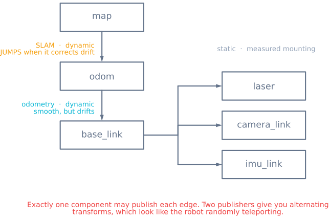
Separating map and odom lets global corrections occur without making the local control frame jump. The names follow ROS conventions, but your robot may add base_footprint, gimbal frames, or articulated links.
Decide who publishes every edge
Write an ownership table before launching nodes:
| Transform | Typical owner | Type |
|---|---|---|
map → odom |
localization or SLAM | Dynamic |
odom → base_link |
odometry estimator | Dynamic |
base_link → laser |
robot description/static broadcaster | Static |
base_link → camera_link |
robot description/static broadcaster | Static |
Exactly one authoritative component should publish each edge. Two publishers produce alternating or conflicting transforms that can look like random pose jumps.
Static transforms describe measured mounting geometry. Put the origin and axis orientation where the sensor model expects them. A camera optical frame uses different axis conventions from a typical robot base frame, so follow the relevant ROS sensor convention rather than guessing from the drawing.
Inspect the live tree
Start with command-line evidence:
ros2 run tf2_tools view_frames
ros2 run tf2_ros tf2_echo odom base_link
ros2 run tf2_ros tf2_echo base_link laser
view_frames generates a graph showing connectivity, publishers, update rate, and timing information. tf2_echo target source reports the transform that converts data from the source frame into the target frame. Swapping the arguments shows the inverse, which is a common source of confusion.
In RViz, set the fixed frame intentionally. If the fixed frame is map but map → odom is absent, displays depending on odometry and sensors cannot be placed even though their own messages are arriving.
Respect measurement timestamps
TF2 stores a history of dynamic transforms. A sensor message stamped at time t should be transformed using the tree at time t, not simply the latest transform. This matters while the robot is moving: using a later pose shifts the observation.
Use the same clock source across nodes. In simulation, all participants must agree on simulated time. On multiple computers, clocks need synchronization appropriate to the sensor timing accuracy.
An “extrapolation into the future” error often means the requested timestamp is newer than the available transform. “Extrapolation into the past” means the requested data is older than the TF2 buffer. Increasing the buffer may help genuinely delayed data, but it does not fix clocks that disagree or timestamps created at the wrong stage.
Verify geometry with simple physical tests
Numbers can look plausible while axes are wrong. Test one relationship at a time:
- Keep the robot stationary and visualize sensor points in
base_link. - Place a target directly in front. Its transformed position should lie on the expected forward axis.
- Rotate the robot in place. A fixed world target should remain fixed in
odomapart from odometry error. - Translate forward. Sensor observations should move consistently with the base pose.
Measure static translations from the chosen origins, not from arbitrary enclosure edges. For a planar robot, a wrong yaw sign can mirror scans and make walls appear to rotate with the vehicle.
Transform data at the consumer boundary
A consumer should state the target frame it needs and ask TF2 to transform the stamped data. Avoid manually copying translation and rotation values into application formulas; that bypasses time synchronization, frame chaining, and established quaternion handling.
If a transform may arrive slightly after the message, use a TF-aware message filter or bounded wait appropriate to the node. Do not block a real-time control loop indefinitely waiting for geometry.
Keep frame IDs free of leading slashes and consistent in spelling and case. Namespaces should be planned for multi-robot systems so robot_1/base_link and robot_2/base_link cannot collide.
Diagnose failures from the error shape
- No connection between frames: an edge is missing or the frame name differs between publisher and message.
- The tree alternates between poses: two nodes publish the same child transform.
- Sensor data is rotated 90° or mirrored: static orientation or optical-frame convention is wrong.
- Data trails behind motion: timestamps are wrong, transforms arrive late, or the consumer uses the latest transform.
- The robot jumps globally but local control is smooth: this may be valid
map → odomlocalization correction. - Local control jumps when localization updates: a global pose is incorrectly being published as
odom → base_link. - RViz shows messages but cannot place them: fixed frame or tree connectivity is wrong.
The pose integrated in differential-drive odometry naturally supplies odom → base_link. The SLAM fundamentals tutorial explains which global estimator supplies map → odom and why the separation matters.
Explore the graph
Part of these builds
Projects and learning paths that include this tutorial.
Further reading