
Tutorial · Beginner · 30 min
Robot Gripper Types and How to Size Grip Force
Parallel, angular, suction and soft grippers compared, then the formula that sizes grip force — including the term almost everyone leaves out of it.
The end effector is the robot
An arm is a positioning system. It is judged on repeatability, reach and speed, and those are the numbers on the datasheet. But nobody buys a robot to position empty air — the job is always done by the thing on the end, and the end effector is where most first builds fail.
This page does the two decisions in order. First pick a type, because that is geometry and it constrains everything after it. Then size the force, because that is arithmetic and there is exactly one formula.
The four types
Parallel (two-finger) grippers
Two jaws that stay parallel as they close, driven by a screw, a rack, a scissor linkage or a pair of servos.
- Good at: anything with two roughly parallel faces. Boxes, blocks, bottles, PCBs, most bench parts.
- Bad at: spheres, cones, anything squashy, anything you must not mark.
- Why people pick it: it is the simplest thing that works and the jaw position is predictable, so the arm’s own calibration carries through to the part.
- Watch out for: the grasp line has to lie inside both friction cones, which as force closure shows is a geometry test that squeezing cannot pass.
This is the type the gripper simulator models, because it is the one almost everyone builds first.
Angular (pivoting jaw) grippers
The jaws swing on a pivot rather than translating. One servo horn straight onto a finger is the cheapest possible gripper and it is an angular one.
- Good at: wide opening range from a small actuator, cheap builds, reaching into a cluttered bin.
- Bad at: predictability. The contact point moves along the finger as it closes, so the lever arm — and therefore the grip force — changes with the object’s width.
- The trap: you size the force for a 40 mm part, then pick up a 20 mm part and get a different force entirely. Measure the lever arm at the width you actually use.
Vacuum (suction) grippers
A cup, a seal, and a pressure difference. Force is ΔP × A, and on a good seal at 60 kPa a 30 mm cup lifts about 42 N.
- Good at: flat, smooth, non-porous, single-sided access. Sheet goods, glass, boxes, phone screens. Fast, cheap per pick, and gentle.
- Bad at: porous (cardboard edges, fabric, raw wood), curved, dusty, oily, or perforated surfaces. And there is no tangential strength worth relying on — a suction grasp shears off sideways long before it pulls off.
- The trap: sizing for the weight and forgetting the acceleration, exactly as below, and then finding the part launches itself off the cup on the first fast move.
Soft and adaptive grippers
Printed flexures, fin-ray fingers, pneumatic bladders, granular jamming. The finger conforms to the object rather than the object conforming to the finger.
- Good at: irregular, delicate, or varied objects. Produce, biological samples, anything where the shape is different every time.
- Bad at: precision. The part ends up wherever the compliance put it, not where you commanded.
- Why they matter even for rigid parts: compliance is what makes the force window aimable at all. A fin-ray finger is a spring in series, and that turns a position command into a force command with usable tolerance — the subject of servo gripper force, stall and compliance.
Choosing
| If the object is… | Use |
|---|---|
| Flat, smooth, accessible from one side | Suction — fastest and cheapest per pick |
| Rigid with two parallel faces | Parallel jaws |
| Rigid, wildly varying width, cheap build | Angular jaws |
| Delicate, irregular, or a different shape each time | Soft / adaptive |
| Ferrous | An electromagnet, and stop reading — it is simpler than all of these |
The most common mistake is picking parallel jaws by default and then fighting the object. If your part is flat and you can reach the top of it, a £4 suction cup and a cheap pump will beat a printed gripper on every axis that matters.
Sizing the force
Now the arithmetic. For a mechanical gripper holding by friction, the required grip force per jaw is:
F = m · (g + a) · SF / (μ · n)| Term | What it is | Where people go wrong |
|---|---|---|
m |
Mass of the object, kg | Fine |
g |
9.81 m/s² | Fine |
a |
Peak acceleration the arm imparts at the tool | Left out entirely. This is the big one |
SF |
Safety factor, 2 minimum | Often 1, i.e. none |
μ |
Friction coefficient at the pad | Optimistic by 2× |
n |
Number of gripping contacts (2 for two jaws) | Sometimes forgotten, doubling the answer |
The acceleration term is not optional
A robot arm that swings a load imparts several g at the tool, and the grasp has to survive the swing, not the pick. Work an egg — 58 g, μ 0.35, safety factor 2:
| Lift | Peak acceleration | Force needed |
|---|---|---|
| Standing still | 0 | 1.63 N |
| 250 mm in 1.5 s | 0.67 m/s² | 1.74 N |
| 250 mm in 0.9 s | 1.85 m/s² | 1.93 N |
| 250 mm in 0.35 s | 5.85 m/s² | 2.59 N |
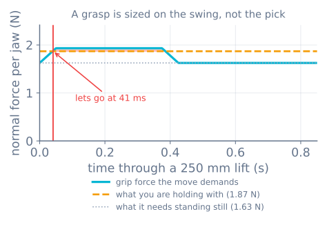
A grasp sized on the bench at 1.7 N passes every static test you can run and then drops the egg 40 ms into a 0.9 s lift — before the arm has moved a centimetre, which is why it reads as “the gripper just let go” rather than as a sizing error. You can watch that exact failure in the gripper simulator by dragging the lift-time slider with everything else held still.
If you do not know a, get it from the move you actually plan. A trapezoidal or S-curve profile gives it to you directly, and a ≈ 4·d/t² is a decent envelope for a point-to-point move of distance d in time t.
Worked example: a 200 g part on a hobby arm
m= 0.2 kg,μ= 0.4 (TPU pad on painted steel),n= 2,SF= 2- The move: 300 mm in 0.6 s, so
a ≈ 4 × 0.3 / 0.36 ≈ 3.3 m/s²
F = 0.2 × (9.81 + 3.3) × 2 / (0.4 × 2) = 6.6 N per jawNow check that against what your actuator can do. An SG90 at 0.176 N·m on a 30 mm finger produces 5.9 N at stall and about 4.1 N continuously — not enough. Options, in increasing order of effort: shorten the lever arm to 18 mm (9.8 N stall, 6.8 N continuous), raise μ with softer pads, slow the move down, or fit a bigger servo. The gripper simulator will do this trade for you live.
The other two walls
Grip force has a floor and it also has two ceilings, and the ceilings are what turn sizing into design:
floor     m(g + a)·SF / (μ·n)        below this it slips
ceiling   min( F_crush , τ·k/L )     above this it is destroyed, or the servo gives up first
F_crush is what the object takes before it deforms. Measure it — a kitchen scale and a few sacrificial parts will get you inside 20%, which is far better than any number you will find online. As a starting point: a strawberry is about 3 N, a paper cup about 4 N, an empty PET bottle about 8 N, a chicken egg about 30 N across its short axis.
The gap between floor and ceiling is the entire engineering problem. It is often much narrower than people expect, and once you divide it by the stiffness of your fingers to get millimetres, it is frequently narrower than one step of your servo — at which point no setting works. That is the subject of the next tutorial, and it is the reason compliant fingers exist.
Suction sizing, briefly
If you went the vacuum route the arithmetic is different and simpler:
F = ΔP · A · (1/SF) A = π·d²/4 for a round cupWith a decent venturi pulling 60 kPa below atmosphere, a 30 mm cup gives 60000 × 0.000707 = 42 N theoretical. Apply a safety factor of 2 vertically and 4 horizontally — the shear strength of a suction grasp is far lower than its pull-off strength, and horizontal moves are what break it. Leaks matter more than cup size: a cup half-off the edge of a box is not half as strong, it is not working.
The mistakes, in the order people make them
- Sizing for the weight, not the move. The acceleration term is usually bigger than gravity on a quick arm.
- Taking μ from a table. The table assumes clean, dry, and flat. Measure yours with a luggage scale and a ramp.
- Forgetting
n. Two contacts share the load; one V-groove contact does not. - Designing to the stall torque. A servo held at stall cooks. Derate to about 70%, and see the stall discussion.
- Ignoring the crush ceiling until something breaks. The floor and the ceiling have to be checked together, or you have only designed half the gripper.
- Fighting a geometry problem with force. If the part squirts out, it is force closure, and squeezing is not the fix.
Next
- Friction, force closure and why two contacts is a bet — the geometry test that force cannot pass
- Servo gripper force, stall and compliance — the window, the servo step, and why stiff fingers fail
- The gripper simulator — drag the numbers above and watch the walls move
- Pick-and-place state machine — once the gripper works, the sequence around it
Explore the graph
Part of these builds
Projects and learning paths that include this tutorial.
Further reading