
Component · Sensor
Raspberry Pi Camera
The camera that plugs into a Raspberry Pi's CSI ribbon rather than USB — a dedicated data lane, autofocus, and the sensor most robot vision code assumes.
What it is
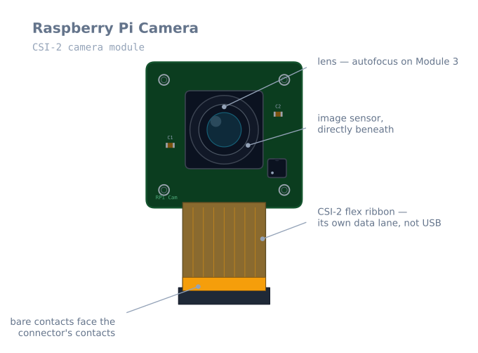
A small sensor board on a flat ribbon cable that connects to the Raspberry Pi’s CSI port — a dedicated camera interface, not USB. That distinction is the whole reason it exists. A robot’s Pi is usually already carrying Wi-Fi, a serial link to a motor controller, and possibly storage on its USB bus; a camera pushing 1080p through the same bus is where that stops working.
For a robot, the camera is the sensor that changes what is possible. Every other sensor on this site reports one number — a distance, an angle, a reflectance. A camera reports a scene, and that is what lets a robot recognise what something is rather than only that something is there.
How it works
Light hits the sensor, and the sensor streams raw rows out over MIPI CSI-2 — a fast, short-range serial link — into the Pi’s image pipeline. The Pi turns those raw rows into a usable image: debayering, white balance, exposure, lens shading correction. On current Raspberry Pi OS this is handled by libcamera, with rpicam-apps on the command line and Picamera2 in Python.
Two consequences matter for robots:
The pipeline costs time. A frame is not available at the instant it was exposed. By the time your code sees it, tens of milliseconds have passed, and a moving robot has moved. Any control loop closed on vision has to be designed around that delay.
Exposure is automatic unless you stop it. Auto-exposure will happily change the brightness of your scene between frames, which is fine for photographs and hostile to a vision algorithm that thresholds on brightness. Lock exposure and gain once the lighting is settled.
When to use it
Reach for a camera when the robot needs to answer a question a scalar sensor cannot:
- Fiducial markers — ArUco tags give a full 3D pose from a single frame, which is the cheapest way to get a robot a real position fix.
- Line following in the real world — a camera sees the line metres ahead, where a reflectance array sees only what is directly beneath it.
- Object recognition — telling a chair from a wall, rather than reading the same 40 cm from both.
- Visual SLAM — building a map from images alone.
Do not add one for obstacle avoidance. A VL53L0X answers “how far?” in 20 ms with three lines of code; a camera answers it worse, slower, and with a hundred times the effort.
Wiring and gotchas
- The ribbon has an orientation. The silver contacts face the board’s connector contacts — on a Pi, that means the blue backing tab faces the USB/Ethernet side. Inserted the wrong way, the camera simply is not detected, and nothing is damaged.
- Lift the connector latch first. Pull the plastic collar up gently, seat the ribbon fully square, then press the collar back down. A ribbon that is in at a slight angle enumerates intermittently, which looks like a faulty camera.
- Pi 5 and Zero need the 22-pin cable. Same camera, narrower connector. Check before you order.
- Keep the ribbon away from motor wiring. It is an unshielded high-speed link running next to whatever else you have crammed into the chassis; motor noise coupled into it shows up as corrupted frames.
- Budget the power. Roughly 250 mA on top of the Pi’s own draw, from the same supply that browns out and corrupts the SD card if you skimp on it.
- Focus is a setting, not just a ring. On Module 3 the autofocus will hunt if the scene is low-contrast. For a robot that always looks at roughly the same distance, set a fixed focus position and stop it hunting mid-manoeuvre.
Choosing a module
| Module | Sensor | Resolution | Focus | Notable for a robot |
|---|---|---|---|---|
| Module 2 | IMX219 | 8 MP | Fixed (manually adjustable) | Cheap, predictable, no autofocus hunting |
| Module 3 | IMX708 | 11.9 MP | Autofocus | Best general choice; lock the focus for robotics |
| Module 3 Wide | IMX708 | 11.9 MP | Autofocus | 102° field of view — much better for navigation |
| HQ Camera | IMX477 | 12.3 MP | C/CS mount lenses | When you need a specific lens or long range |
| Global Shutter | IMX296 | 1.6 MP | C/CS mount | The one that matters most for a moving robot |
The global-shutter module deserves a proper explanation, because rolling shutter is the single most under-appreciated problem in robot vision.
A rolling shutter sensor exposes rows one after another rather than all at once, so the top of a frame is captured a few milliseconds before the bottom. On a stationary camera this is invisible. On a robot turning at 90°/s, the top and bottom of the frame were taken from different angles, and straight vertical lines come out skewed.
For a marker-pose pipeline this is not cosmetic. An ArUco tag’s corners are used to solve for its pose, and if the corners were captured at four slightly different robot orientations, the computed pose is wrong in a way no amount of calibration corrects. If your robot does vision while moving, a global-shutter sensor is the fix, and it is worth the lower resolution.
Setting it up so the images are usable
Automatic exposure, gain and white balance are excellent for photography and actively harmful for a vision algorithm. They change the numbers your thresholds depend on between frames, for reasons unconnected to the scene.
from picamera2 import Picamera2
import time

picam = Picamera2()

# Small frames. 640x480 is plenty for markers and lines, and the pipeline
# cost scales with pixel count.
config = picam.create_video_configuration(
    main={"size": (640, 480), "format": "RGB888"},
    controls={"FrameDurationLimits": (33333, 33333)},   # lock to 30 fps
)
picam.configure(config)
picam.start()

# Let auto-exposure settle on the real scene, then freeze it.
time.sleep(2)
metadata = picam.capture_metadata()
picam.set_controls({
    "AeEnable": False,
    "AwbEnable": False,
    "ExposureTime": metadata["ExposureTime"],
    "AnalogueGain": metadata["AnalogueGain"],
    "AfMode": 0,                 # manual focus
    "LensPosition": 2.0,         # dioptres: 1/distance_in_metres
})

while True:
    frame = picam.capture_array()
    # ... your processing here
The LensPosition value is in dioptres — the reciprocal of the focus distance in metres.
A robot looking at things about 50 cm away wants 2.0; one metre wants 1.0; infinity is
0.0. Setting it explicitly stops the autofocus hunting mid-manoeuvre, which on a moving
robot produces a second or two of blurred frames at exactly the wrong moment.
Resolution, frame rate, and latency
Resolution is the setting people leave too high, and it costs more than they expect.
| Resolution | Pixels | Relative processing cost | Suitable for |
|---|---|---|---|
| 320×240 | 77 k | 1× | Line following, blob tracking |
| 640×480 | 307 k | 4× | ArUco markers, most robot vision |
| 1280×720 | 922 k | 12× | Small or distant markers |
| 1920×1080 | 2.07 M | 27× | Recording, rarely for real-time control |
A Pi 4 doing ArUco detection at 640×480 manages a comfortable 30 fps. At 1920×1080 the same pipeline drops to single figures, and every frame is stale by the time it is processed. Use the smallest resolution that still resolves the feature you care about, and remember that detection distance scales with resolution — if a marker is not detected far enough away, raising the resolution genuinely helps, at that cost.
The latency budget
This is what makes vision-based control hard, and it is worth writing out:
| Stage | Typical |
|---|---|
| Exposure | 10–30 ms |
| Sensor readout and CSI transfer | 5–15 ms |
| ISP pipeline (debayer, white balance) | 5–10 ms |
| Your processing | 10–50 ms |
| Total, image to decision | 30–105 ms |
A robot moving at 0.3 m/s travels 1–3 cm during that window; turning at 90°/s, it rotates 3–9°. Any control loop closed on vision is acting on where the robot was, and if you tune it as though the measurement were current, it will oscillate.
The practical answers are the same ones used everywhere else in this situation: run the vision loop slower than the control loop and use it to correct a faster dead-reckoning estimate, or predict forward by the known latency before using the measurement. This is exactly the structure the path following path builds for GPS, and for the same reason.
Mounting it on a robot
Rigidly. Camera calibration produces intrinsic parameters — focal length, principal point, distortion — that are properties of that camera in that mount. A bracket that flexes as the robot accelerates invalidates the calibration continuously, and pose estimates wander for no visible reason.
Away from the motor wiring. The CSI ribbon is an unshielded high-speed differential link. Running it alongside motor leads couples switching noise into it, which appears as corrupted frames or a camera that intermittently disappears.
With the ribbon strain-relieved. The flat cable’s connector is not designed for repeated flexing, and a robot vibrates constantly. Tape the ribbon down near both ends so vibration does not work the connector loose.
Angled down slightly for a ground robot. A camera pointed at the horizon spends most of its pixels on the ceiling. Ten to twenty degrees down puts the useful part of the scene — the floor ahead, and anything on it — in the middle of the frame.
Troubleshooting
| Symptom | Likely cause | Fix |
|---|---|---|
| Camera not detected at all | Ribbon in backwards | Silver contacts toward the board’s contacts |
| Detected intermittently | Ribbon not fully seated or square | Lift the latch, reseat fully, press down |
No cameras available on a Pi 5 |
Wrong cable width | Pi 5 and Zero need the 22-pin cable |
| Frames corrupted or torn | Motor noise on the ribbon | Route it away from motor leads; strain-relieve it |
| Brightness changes between frames | Auto-exposure still on | Lock exposure and gain after a settling period |
| Image goes soft mid-manoeuvre | Autofocus hunting | Set AfMode: 0 and a fixed LensPosition |
| Vertical lines skewed while turning | Rolling shutter | Slow the turn, or use a global-shutter module |
| Frame rate collapses under load | Resolution too high | Drop to 640×480; check for thermal throttling |
| Pose estimates drift with no cause | Camera mount flexing | Mount rigidly; recalibrate |
| Pi reboots when the camera starts | Supply cannot cover the extra ~250 mA | Better supply — this corrupts SD cards |
Camera or a ranging sensor?
| Camera | VL53L0X / HC-SR04 | |
|---|---|---|
| Answers | What is there, where, and its orientation | How far to the nearest thing |
| Latency | 30–100 ms | 20–60 ms, with no processing |
| Code required | A vision pipeline | Three lines |
| Compute | A Pi-class processor | Any microcontroller |
| Fails when | Dark, backlit, motion-blurred | Specific surfaces (see each page) |
| Cost | $25–50 plus a Pi | $2–5 |
The honest rule: do not add a camera for obstacle avoidance. A ranging sensor answers that question faster, more cheaply, and more reliably, and every hour spent making a camera do it is an hour not spent on the thing only a camera can do.
Add a camera when you need to know what something is, or where you are — recognising an object, reading a fiducial marker to get an absolute pose fix, or following a line the robot can see metres ahead rather than only underneath itself. Those are genuinely impossible with a scalar sensor, and they are worth the whole pipeline.
Explore the graph
Used in these builds
Projects, learning paths, and simulators that include the Raspberry Pi Camera.
Questions
Raspberry Pi Camera FAQ
Is a Pi camera better than a USB webcam for robotics?
For a robot, usually yes, and the reason is the connector rather than the picture. A CSI camera has its own data lane straight into the Pi's image pipeline, so it does not compete with a Wi-Fi dongle or a serial link for USB bandwidth, and its frame timing is far more predictable. A webcam is the better choice only when you need a long cable — CSI ribbons are short and fragile — or when you want the camera to work unchanged on a laptop.
Which Raspberry Pi camera should I buy for a robot?
Camera Module 3 for most robots — autofocus, a wide-angle option, and current software support. Take the wide (102°) version if the robot needs to see things close to itself, which is nearly always true for navigation. Choose the Global Shutter camera instead if the robot moves fast while looking, and the HQ camera if you need a specific lens. Camera Module 2 is still fine and cheaper if fixed focus suits you.
Why does my camera image skew when the robot turns?
Rolling shutter. The sensor reads out one row at a time rather than capturing the whole frame at once, so anything that moves during readout is recorded at a slightly different place on each row — a turn shears straight lines into slanted ones. It matters because pose estimation assumes one instant per frame. Shorten the exposure, slow the robot while measuring, or use the Global Shutter camera, which captures every row at once.
Does the Pi 5 use the same camera cable?
No, and this catches almost everyone. Pi 5 and the Zero models use a narrower 22-pin connector, while Pi 4 and earlier use the 15-pin one that ships with most cameras. The camera itself is the same; you need the right ribbon or an adapter. The Pi 5 also has two camera connectors, so it can run a stereo pair.
Do I still use the picamera library?
No — the original `picamera` module was written against a camera stack that no longer exists on current Raspberry Pi OS. Use **Picamera2**, which sits on libcamera, or capture through OpenCV once the camera appears as a V4L2 device. Most tutorials older than a few years are written for the dead API, which is the usual reason a copied snippet fails immediately on a fresh install.
Further reading