
Component · Comms
HC-05 Bluetooth Module
The HC-05 adds Bluetooth serial to a robot—pair it with your phone to drive the robot or stream data, using the same TX/RX pins as a wired link.
What it is
The HC-05 is the simplest way to make a robot wireless. It’s a Bluetooth module that behaves like a serial cable with no cable: your microcontroller reads and writes bytes on its TX/RX pins exactly as it would over USB, but the other end is a phone or laptop paired over Bluetooth. Send an F from a phone app and your robot drives forward—no Wi-Fi, no network, no accounts.
How it works
The HC-05 implements the Bluetooth Serial Port Profile (SPP). Once paired, everything the module receives over the air appears on its TX pin, and everything you send to its RX pin goes over the air to the paired device. Your code just uses the serial port—Serial.read() / Serial.print()—and the wireless link is invisible. Configuration (name, baud, master/slave role) is done with AT commands in a separate command mode, but for most robots the defaults work out of the box.
When to use it
Reach for an HC-05 when you want to command or monitor a robot without a tether:
- Phone-controlled robots — a Bluetooth app sends drive commands the robot reads over serial and turns into motor control.
- Live telemetry — stream sensor values or odometry back to a laptop while the robot runs.
- Wireless tuning — adjust parameters on the fly instead of re-flashing.
If the robot already uses an ESP32, you don’t need an HC-05—the ESP32 has Bluetooth and Wi-Fi built in. The HC-05 is the add-on that gives an Arduino Uno the same wireless trick.
Wiring and gotchas
- Cross the serial lines: module TX → board RX, module RX → board TX. Getting this backwards is the #1 “it won’t connect” cause.
- Divide the RX pin down to 3.3 V from a 5 V board like the Uno.
- Free the hardware serial port while uploading code, or use a software-serial pin pair—the module and the USB programmer can’t share the Uno’s one hardware UART.
- Pair first (PIN usually 1234/0000); the onboard LED shows connection state.
Pinout
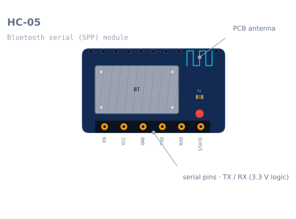
| Pin | Name | What it does |
|---|---|---|
| 1 | EN / KEY |
Held HIGH at power-on to enter AT command mode |
| 2 | VCC |
3.6–6 V. The breakout regulates to 3.3 V internally |
| 3 | GND |
Ground |
| 4 | TXD |
Module transmits. Goes to the microcontroller’s RX |
| 5 | RXD |
Module receives. 3.3 V logic — divide a 5 V signal |
| 6 | STATE |
HIGH when a device is connected. Genuinely useful, usually ignored |
The STATE pin deserves better than it gets. A robot that reads it knows when its phone has
walked out of range, which is the difference between stopping safely and driving into a wall
while waiting for a command that will never arrive.
Wiring it to an Arduino
The two mistakes here account for most “it will not connect” reports.
| HC-05 | Arduino Uno | Note |
|---|---|---|
| VCC | 5 V | The onboard regulator handles it |
| GND | GND | |
| TXD | Pin 10 (SoftwareSerial RX) | Module TX → board RX. Cross them |
| RXD | Pin 11 via divider (SoftwareSerial TX) | Board TX → module RX, through 2:1 divider |
| EN | Leave open | Only needed for AT mode |
| STATE | Any digital pin | Optional connection check |
Cross the serial lines
TX talks, RX listens. Two devices that both talk on the wire you connected achieve nothing, and there is no error — the module pairs fine, the LED goes solid, and no data ever moves. Module TX goes to board RX. Module RX goes to board TX.
Divide the RX line
RXD is a 3.3 V input and an Arduino Uno drives 5 V. Two resistors:
Arduino TX ──── 1 kΩ ──┬── HC-05 RXD
                        │
                      2 kΩ
                        │
                       GND
TXD needs no divider in the other direction — the module’s 3.3 V output clears the Uno’s
3.0 V high threshold.
Do not use pins 0 and 1
The Uno has one hardware UART and the USB programmer already owns it. Wire the module there
and uploads fail while it is connected, serial monitor output goes to the module, and
debugging becomes impossible. Use SoftwareSerial on two other pins.
Minimal working code
#include <SoftwareSerial.h>

SoftwareSerial bt(10, 11);      // RX (from module TX), TX (to module RX)
const int STATE_PIN = 8;

void setup() {
  Serial.begin(115200);         // USB, for debugging
  bt.begin(9600);               // HC-05 default in data mode
  pinMode(STATE_PIN, INPUT);
}

void loop() {
  // Lose the link, stop the robot. Do this before reading commands.
  if (digitalRead(STATE_PIN) == LOW) { stopMotors(); }

  if (bt.available()) {
    char c = bt.read();
    switch (c) {
      case 'F': driveForward();  break;
      case 'B': driveBackward(); break;
      case 'L': turnLeft();      break;
      case 'R': turnRight();     break;
      case 'S': stopMotors();    break;
    }
    Serial.print("cmd: "); Serial.println(c);   // echo to USB for debugging
  }
}
The connection check at the top of the loop is the part most tutorials leave out, and it is the part that stops a runaway. Bluetooth range is about 10 m and walls cut it sharply; a robot that keeps executing its last command after the link drops will keep going until it hits something.
AT command mode
Changing the module’s name, baud rate or PIN needs AT mode, and entering it has a specific sequence that nothing about the module makes obvious.
- Power the module off.
- Hold
ENHIGH (or press and hold the small button, if your board has one). - Power it on while
ENis held. - The LED now blinks slowly — roughly once every two seconds — rather than rapidly.
- Talk to it at 38400 baud, not 9600, with both newline and carriage return.
AT                    -> OK
AT+NAME=LineBot       -> OK      set the name shown when pairing
AT+PSWD="1234"        -> OK      set the pairing PIN (quotes on newer firmware)
AT+UART=115200,0,0    -> OK      data-mode baud rate
AT+ROLE=0             -> OK      0 = slave (normal), 1 = master
AT+ADDR?              -> +ADDR   the module's own address
Two gotchas: AT mode is always 38400 regardless of the data-mode baud you set, and the LED blink rate is the only reliable indication you are in it. Fast blink means data mode and your AT commands will simply be transmitted over the air to whatever is paired.
HC-05 or HC-06?
They look identical and are sold interchangeably, and there is one real difference.
| HC-05 | HC-06 | |
|---|---|---|
| Role | Master or slave | Slave only |
| Can initiate a connection | Yes | No |
| AT mode | Via EN pin, 38400 |
Any time while unpaired, at the data baud |
| Price | Slightly more | Slightly less |
If the module only ever needs to accept a connection from a phone, an HC-06 is fine. If you ever want two robots to talk to each other, or a robot to connect to a module rather than wait to be connected to, you need the HC-05’s master role.
Troubleshooting
| Symptom | Likely cause | Fix |
|---|---|---|
| Pairs, but no data moves | TX/RX not crossed | Module TX → board RX, module RX → board TX |
| Garbage characters | Baud mismatch | Both ends at 9600, or set both to the same value |
| Uploads fail while connected | Module on pins 0/1 | Move to SoftwareSerial pins |
| AT commands do nothing | Not actually in AT mode | Hold EN during power-on; check for the slow blink |
| AT mode gives no response | Using the data baud | AT mode is 38400, always |
| Will not pair | Wrong PIN | Try 1234 then 0000 |
| Drops out a few metres away | Class 2 range plus walls | Expected; use the STATE pin to fail safe |
| Robot keeps driving after disconnect | No link check | Read STATE and stop on LOW |
| Works on USB power, not on battery | Supply sag | The radio’s transmit bursts need a stiff 5 V |
HC-05 or an ESP32?
If you are choosing components rather than using what you have, this is the real decision.
| HC-05 + Arduino | ESP32 | |
|---|---|---|
| Wireless | Bluetooth Classic SPP | Wi-Fi and Bluetooth, built in |
| Extra hardware | A module, a divider, two pins | None |
| Control interface | A serial byte stream | A web page the robot serves itself |
| Range | ~10 m | ~50 m on Wi-Fi, or anywhere with a network |
| Phone app needed | Yes — a generic Bluetooth terminal | No — any browser |
| Learning value | Serial protocols, the plainest possible link | Networking, which is a bigger subject |
The HC-05 is the right answer when you already have an Arduino and want the shortest path to a wireless robot. It is genuinely simple: a byte in, a byte out, no networking concepts at all. For a new build where wireless is a requirement, an ESP32 does more for less and needs no extra parts — and a robot that serves its own control page needs no app installed on anyone’s phone.
Explore the graph
Used in these builds
Projects, learning paths, and simulators that include the HC-05 Bluetooth Module.
Compare
Alternatives
Questions
HC-05 Bluetooth Module FAQ
What is an HC-05?
The HC-05 is a Bluetooth module that turns a wireless connection into a plain serial (UART) link. To your microcontroller it looks exactly like a wired serial cable—you read and write bytes on TX/RX—except the other end is your phone or PC over Bluetooth. It's the easiest way to control a robot wirelessly.
How do you connect an HC-05 to an Arduino?
Power VCC and GND, then cross the serial lines—module TX to Arduino RX, module RX to Arduino TX. Because the HC-05's RX pin is 3.3 V, drop the Arduino's 5 V TX with a voltage divider. Then anything you print over serial goes wirelessly to the paired phone, and vice versa.
What is the range of the HC-05?
About 10 metres line of sight—it's a Class 2 Bluetooth device. Walls and interference cut that down. That's plenty for driving a robot around a room from your phone, but for long-range control you'd move to Wi-Fi or a dedicated radio.
How do you pair HC-05 modules?
To pair with a phone, power the module, open your phone's Bluetooth settings, select the HC-05, and enter the PIN (usually 1234 or 0000). To pair two HC-05s to each other, set one as master and one as slave with AT commands and bind them by address.
How do you program the HC-05?
The HC-05 has two modes. In data mode it simply passes serial bytes through. To change its name, baud rate, or master/slave role, put it in AT command mode—hold the EN/KEY pin high at power-up—and send AT commands over serial.
Further reading