
Component · Controller
8051 Microcontroller
The 8051 is the 8-bit microcontroller most engineering courses still teach first. What the architecture gives you, and what it makes you build by hand.
What it is
The 8051 is not a board and not really a single chip—it is an architecture. Intel published it in 1980, then licensed the core so widely that the part you actually buy today comes from someone else. In a lab kit that is almost always Atmel’s AT89S52: an 8051 core with 8 KB of flash, 256 bytes of RAM, three timers, and in-system programming over four pins.
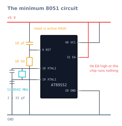
What arrives is a 40-pin DIP and nothing else. No USB, no regulator, no bootloader, no pinMode(). Before it will execute a single instruction you have to give it a crystal, two load capacitors, a reset network, and a connection from EA to +5 V. That bare quality is the entire reason it is still on the syllabus: there is no layer between your code and the silicon to explain away behaviour you do not understand.
How it works
The 8051 is a Harvard machine: program memory and data memory are separate address spaces, reached by different instructions. Code lives in flash; variables live in 256 bytes of internal RAM that is itself divided into four register banks, a bit-addressable window, and whatever is left for your stack.
Timing is unusually easy to reason about. One machine cycle is twelve oscillator periods, and most instructions take one or two of them. At 11.0592 MHz that is 1.085 µs per cycle, so you can count instructions and know—not estimate—how long a loop takes. Very few modern parts let you do that.
The 32 I/O pins are grouped into four ports with distinct personalities:
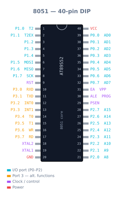
- P1 is the only straightforward one—eight general-purpose pins with internal pull-ups.
- P3 doubles every pin with an alternate function: serial RXD/TXD, the two external interrupts, the two timer inputs, and the external memory read and write strobes.
- P2 carries the high address byte when external memory is attached.
- P0 is open-drain. Without external pull-up resistors it cannot output a logic high at all, and it also carries the multiplexed low address and data byte.
What the chip does not have matters just as much: no analog inputs and no PWM hardware. Reading a sensor voltage needs an external ADC, and varying a motor’s speed means generating the waveform yourself from a timer interrupt.
When to use it
Reach for the 8051 when the point is learning the machine—a microcontrollers course, a university mini-project, or your own curiosity about what analogWrite() actually does. Writing a software PWM generator teaches more in an afternoon than a year of calling a library that hides it.
Choose almost anything else when the point is the robot. An Arduino Uno gives you hardware PWM, analog inputs, and a library for every sensor you will meet; an ESP32 adds Wi-Fi and far more memory. Both cost about the same as an 8051 development board. Picking the 8051 for a project that needs to work rather than to teach means rebuilding, by hand, things the alternatives hand you for free.
Common gotchas
- EA must be tied to +5 V. Pin 31 selects internal or external program memory. Floating or grounded, the chip silently fetches from external memory that is not there and does nothing at all—no error, no light, no clue. This is the single most common reason a first 8051 board appears dead.
- Reset is active HIGH. Unlike almost every other microcontroller you will meet, the 8051 resets when RST is pulled up. The standard power-on circuit is a 10 µF capacitor from +5 V to RST and a 10 kΩ resistor from RST to ground.
- Port 0 needs external pull-ups. It is open-drain. Wire 10 kΩ resistors to +5 V or it will never read or drive a high.
- Pins sink, they do not source. The internal pull-up supplies only tens of microamps, while the pull-down transistor sinks milliamps. LEDs go anode-to-supply, cathode-to-pin, and a
0turns them on. Wiring one the other way round produces a very faint glow and a lot of confusion. - The stack starts at 08h, on top of register bank 1. The stack pointer resets to 07h. If you switch to bank 1 without moving SP first, your registers and your return addresses occupy the same bytes.
Why 11.0592 MHz, of all numbers
That crystal frequency looks arbitrary and is one of the most deliberate choices in the whole architecture.
The 8051 generates its serial baud rate by overflowing Timer 1 in 8-bit auto-reload mode:
baud = (2^SMOD / 32) x (oscillator / 12) / (256 - TH1)With SMOD = 0 and an 11.0592 MHz crystal, targeting 9600 baud:
TH1 = 256 - (11059200 / (12 x 32 x 9600)) = 256 - 3 = 253 = 0xFDExactly 3. No rounding, no error. Every standard baud rate — 1200, 2400, 4800, 9600, 19200 — comes out as a whole number of timer reloads.
Now try a round 12 MHz crystal:
TH1 = 256 - (12000000 / 3686400) = 256 - 3.26 -> must round to 3
actual baud = 10417, against a target of 9600 -> 8.5% error
Serial links tolerate about 2–3% of total error between the two ends. At 8.5% the framing drifts within a byte and every character arrives corrupted. This is why 11.0592 MHz exists, why it is on every 8051 lab board, and why substituting the 12 MHz crystal in the drawer produces a chip that works perfectly until you try to print something.
The trade is that timing arithmetic becomes awkward: a machine cycle is 1.085 µs rather than a round 1 µs. A 12 MHz crystal gives exactly 1 µs cycles and unusable serial. Pick according to which one your project needs.
Timers, and generating PWM by hand
The 8051 has three 16-bit timers and no PWM hardware at all. Varying a motor’s speed means generating the waveform yourself, and doing it is genuinely the best thing about learning on this chip.
The timers have four modes; two matter:
| Mode | Width | Reload | Use it for |
|---|---|---|---|
| 0 | 13-bit | Manual | Legacy; ignore it |
| 1 | 16-bit | Manual | Long, precise delays. Must reload in the ISR |
| 2 | 8-bit | Automatic | Baud rates, and any fixed-period tick |
| 3 | Split T0 | — | When you need a third timer badly |
Mode 2 is the one to reach for when you want a steady tick, because the reload happens in hardware and no ISR jitter creeps into the period.
A software PWM generator on Timer 0, at roughly 1 kHz with 100 steps of resolution:
#include <reg52.h>

sbit MOTOR_L = P1^0;
sbit MOTOR_R = P1^1;

volatile unsigned char dutyL = 0, dutyR = 0;   // 0..99
volatile unsigned char tick  = 0;

void timer0_isr(void) interrupt 1 {
    /* Mode 1 is not self-reloading: put the value back first, before
       anything else, or the period stretches by the ISR's own length. */
    TH0 = 0xFF; TL0 = 0xA4;                    /* ~10 us at 11.0592 MHz */

    if (++tick >= 100) tick = 0;               /* 100 ticks = ~1 ms period */

    MOTOR_L = (tick < dutyL) ? 1 : 0;
    MOTOR_R = (tick < dutyR) ? 1 : 0;
}

void main(void) {
    TMOD = (TMOD & 0xF0) | 0x01;               /* Timer 0, mode 1 */
    TH0  = 0xFF; TL0 = 0xA4;
    ET0  = 1;                                  /* enable timer 0 interrupt */
    EA   = 1;                                  /* global interrupt enable */
    TR0  = 1;                                  /* start */

    dutyL = 70; dutyR = 70;
    while (1) { }                              /* PWM runs entirely in the ISR */
}
Two things are worth taking from that. Reload first, always — in mode 1 the timer keeps counting from zero after an overflow, so every instruction executed before the reload adds to the next period. And the cost is real: this ISR fires 100,000 times per second, and at 1.085 µs per machine cycle a dozen-instruction handler consumes a noticeable slice of everything the chip can do. That budget is exactly what a hardware PWM peripheral buys you, and you do not appreciate it until you have paid it by hand.
The port current budget
This catches people because the 8051’s ports are asymmetric in a way modern parts are not.
| Sink (output LOW) | Source (output HIGH) | |
|---|---|---|
| Per pin, P1/P2/P3 | ~10 mA | ~60 µA (internal pull-up only) |
| Per pin, P0 | ~10 mA | 0 — open drain, no pull-up at all |
| Per port, total | ~26 mA | — |
| Whole chip | ~71 mA | — |
Sixty microamps is not a typo. The internal pull-up is a weak resistor, not a driver, so a pin outputting HIGH can supply roughly a thousandth of what it can sink.
Three consequences follow directly:
LEDs go cathode to the pin, anode through a resistor to +5 V, and writing 0 lights them.
Wired the other way they glow very faintly, which reads as a dim or faulty LED rather than a
misunderstanding.
Never drive anything directly. Not a relay, not a buzzer at volume, not a motor. Use a transistor, a ULN2003 driver array, or a proper motor driver.
Port 0 needs external pull-ups — 10 kΩ to +5 V on every pin you intend to use as I/O. Without them it cannot output a high or read one reliably, and it is the port most lab boards route to the LCD.
Memory, and where the 256 bytes go
Eight kilobytes of flash sounds tight and rarely is. 256 bytes of RAM is the real constraint, and it is not a flat 256 bytes:
| Address | Size | What lives there |
|---|---|---|
| 00h–1Fh | 32 bytes | Four register banks, R0–R7 each |
| 20h–2Fh | 16 bytes | Bit-addressable — 128 individually addressable bits |
| 30h–7Fh | 80 bytes | General scratch, and where the stack usually goes |
| 80h–FFh | 128 bytes | Indirect addressing only (SFRs occupy the direct space) |
The stack pointer resets to 07h, which puts the stack immediately on top of register bank 1.
If you switch to bank 1 without moving SP first, your registers and your return addresses
share bytes, and the failure is a spectacular one: the program returns to a random address.
SP = 0x30; as the first line of main() is standard practice.
The bit-addressable region is worth knowing about because it is genuinely elegant. Any bit in 20h–2Fh can be set, cleared or tested in a single instruction, which makes state flags free:
bit lineDetected;      /* the compiler allocates this in 20h-2Fh */
bit motorEnabled;      /* one bit each, one instruction to test */
Eight of those cost one byte, and testing one is a single machine cycle. On a chip with 256 bytes of RAM that matters.
Troubleshooting
| Symptom | Likely cause | Fix |
|---|---|---|
| Chip does nothing at all | EA floating or grounded |
Tie pin 31 to +5 V. Check this first, every time |
Chip does nothing, EA is high |
No crystal oscillation | Check the 33 pF load capacitors and the crystal’s solder joints |
| Resets constantly | RST held high | Reset is active HIGH here — check the 10 µF / 10 kΩ network |
| Port 0 reads and writes nothing | Open drain, no pull-ups | 10 kΩ from each pin to +5 V |
| LED very dim | Wired to source current | Cathode to the pin; write 0 to light it |
| Serial prints garbage | 12 MHz crystal | Use 11.0592 MHz — 12 MHz gives 8.5% baud error |
| Serial works one way only | TX/RX not crossed, or no common ground | Cross them; tie grounds |
| Program returns to nowhere | Stack overlapping register bank 1 | SP = 0x30; at the top of main() |
| PWM period jitters | Reloading the timer late in the ISR | Reload as the first statement, or use mode 2 |
| Erratic behaviour as code grows | Out of RAM | 256 bytes total; check the linker map |
| Programmer cannot see the chip | ISP pins in use, or no reset control | Free P1.5–P1.7 and RST during programming |
8051 or a modern microcontroller?
| 8051 (AT89S52) | Arduino Uno | ESP32 | |
|---|---|---|---|
| Flash / RAM | 8 KB / 256 B | 32 KB / 2 KB | 4 MB / 520 KB |
| Hardware PWM | None | 6 channels | 16 channels |
| Analog input | None | 6 × 10-bit | 18 × 12-bit |
| Serial baud | Needs the right crystal | Any | Any |
| Libraries | Write it yourself | Thousands | Thousands |
| What you learn | The machine | The project | The system |
The honest position: the 8051 is a teaching part, and an excellent one. Writing a software PWM generator, calculating a baud reload by hand, and discovering that a port pin cannot source current teaches you what every modern peripheral is actually doing for you. That understanding transfers permanently, and it is why the architecture is still on syllabuses forty-five years after Intel published it.
For a robot that has to work, choose almost anything else. Building an 8051 line follower means writing the PWM, adding an external ADC or using comparator-output sensors, and hand-computing every timing constant — all of which an Uno provides for the same money. Do it when the point is to understand the machine. Reach for an Uno when the point is the robot.
Explore the graph
Used in these builds
Projects, learning paths, and simulators that include the 8051 Microcontroller.
Compare
Alternatives
Questions
8051 Microcontroller FAQ
What is the 8051 microcontroller?
The 8051 is an 8-bit microcontroller architecture Intel introduced in 1980 and later licensed widely, so today you buy it as a compatible chip such as Atmel's AT89S52 rather than as an Intel part. It packs a CPU, flash memory, RAM, timers, a serial port, and 32 I/O pins into one 40-pin chip, and it remains the standard teaching microcontroller across most engineering syllabi.
Why is the 8051 still taught if it is from 1980?
Because nothing hides from you. There is no core library, no board abstraction, and no hardware PWM—so to blink an LED you set a bit in a port register, and to dim one you write a timer interrupt that counts ticks yourself. That makes it a poor choice for shipping a product and an excellent one for understanding what every other microcontroller is doing on your behalf.
What is the difference between the 8051 and an Arduino?
An Arduino Uno is a board built around an ATmega328P; the 8051 is a bare chip you must surround with a crystal, a reset circuit, and a programmer. The Arduino gives you hardware PWM, analog inputs, a USB bootloader, and a huge library ecosystem. The 8051 gives you none of those—it has no ADC and no PWM at all—which is exactly why courses use it to teach the fundamentals.
Why does the 8051 use an 11.0592 MHz crystal?
Because it makes serial baud rates exact. The UART divides the machine-cycle clock, and 11.0592 MHz divides down to precisely 9600 baud, while a round 12 MHz crystal lands about 8.5% off and corrupts serial data. The odd-looking number is chosen for arithmetic, not for speed.
How many ports does the 8051 have?
Four 8-bit ports—P0, P1, P2, and P3—for 32 I/O pins in total. They are not interchangeable: P0 has no internal pull-ups and needs external resistors, P3 carries the serial, interrupt, and timer pins as alternate functions, and P0 and P2 double as the address and data bus if you attach external memory.
Why does my 8051 program do nothing after I flash it?
Check the EA pin (pin 31) first. Tied to ground or left floating, the chip fetches its program from external memory that is not there, so it runs nothing at all and gives no error. EA must be connected to +5 V to run code from internal flash. The next two suspects are a missing reset circuit and the crystal's two load capacitors.
Can you program the 8051 in C?
Yes, and most courses now do. Keil C51 is the industry-standard compiler and SDCC is a free open-source alternative. C is far more productive than assembly here, but the 8051 rewards knowing what the compiler emits—an innocent-looking multiply or a large local array costs much more on a chip with 256 bytes of RAM than it does elsewhere.
Is the 8051 still used in real products?
Yes, though rarely as a visible standalone chip. 8051-compatible cores are embedded inside countless devices—USB controllers, touch sensors, remote controls, and radio modules—because the core is tiny, well understood, and free of licensing friction. You will meet it far more often as a block inside another chip than as the 40-pin DIP on your lab bench.
Further reading